
Installation guide

7-49
Network Processing Engine and Network Services Engine Installation and Configuration
OL-4448-08
Chapter 7 NPE-G1 and NPE-G2 Installation and Configuration Information
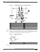
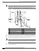
Enabling the Second Processor on the NPE-G1
Gi0/1.201 201 up RX punts 29
Gi0/1.202 202 up
Gi0/1.206 206 up
Gi0/1.2002 602 up RX punts 26114
Gi0/1.2004 604 up
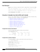
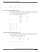
Using the show mpf interface GigabitEthernet 0/1 Command
The following example displays the interface information for GigabitEthernet 1/0, subinterface number
100. However, all Gigabit Ethernet interface and subinterface information is displayed because MPF
does not recognize the subinterface number, unless it is a VLAN number.
Router# show mpf interface GigabitEthernet 0/1.100
Name Index State Counter Count
Gi0/1 0 up RX packets 1004
RX bytes 158632
TX packets 5004
TX bytes 790632
RX punts 32996
TX punts 86062
Gi0/1 1 up
Gi0/1.100 100 up RX packets 1004
RX bytes 158632
TX packets 5004
TX bytes 790632
RX punts 25
Gi0/1.101 101 up
Gi0/1.102 102 up
Gi0/1.105 105 up
Gi0/1.106 106 up
Gi0/1.107 107 up
Gi0/1.200 200 up
Gi0/1.201 201 up RX punts 29
Gi0/1.202 202 up
Gi0/1.206 206 up
Gi0/1.2002 602 up RX punts 26142
Gi0/1.2004 604 up
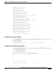
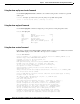
Using the show mpf interface GigabitEthernet 01/100 Command
The following example displays the interface information for VLAN number 100 on the GigabitEthernet
0/1 interface, including up state, receiving packet count, receiving bytes count, transmitting packet
count, transmitting bytes count, and receiving punts count.
Router# show mpf interface GigabitEthernet 0/1 100
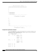
Name Index State Counter Packets Bytes
Gi0/1.100 100 up RX total 963 151050
RX punt 5 475
TX total 956 150449
IP Multi-Processor Forwarding is enabled