
Installation guide

7-44
Network Processing Engine and Network Services Engine Installation and Configuration
OL-4448-08
Chapter 7 NPE-G1 and NPE-G2 Installation and Configuration Information
Installing the NPE-G1 or NPE-G2
–
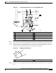
Each AC-input power cable is connected and secured with the cable-retention clip (AC-input
power supplies only).
–
For a Cisco 7200 VXR router, each DC lead is connected and secured to the power supply
faceplate with a cable tie.
–
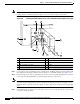
For a Cisco uBR7246VXR router, each DC lead is connected with M4 nuts for the grounding
receptacle and the strain-relief cover over the +V and –V leads (DC-input power supplies only).
–
Each DC lead is connected and secured to the power source (DC-input power supplies only).
–
Ensure that the tape (that you applied earlier) is removed from the circuit breaker switch handle,
and power is restored by moving the circuit breaker handle to the on (|) position (DC-input
power supplies only).
–
The console terminal is turned on.
Caution When the power switch on a Cisco uBR7200 series power supply is turned to the off (O) position, the
power supply enters a reset cycle for 90 seconds. Wait at least 90 seconds before turning the power
switch back to the on (|) position. If you do not wait the full 90 seconds, the power supply does not
restart.
Step 2 At the rear of the router, place the power switch on the power supply in the on (|) position. Repeat this
step if a second power supply is installed in the router. The green OK LED on the power supply turns on.
Note When powering on the router, wait a minimum of 30 seconds before powering it off again.
Step 3 Listen for the fans; you should immediately hear them operating.
Step 4 During the boot process, observe the system LEDs. The LEDs on most of the port adapters go on and
off in an irregular sequence. Some may go on, go off, and go on again for a short time. On the NPE-G1
or NPE-G2 and the I/O controller, the POWER OK LED goes on immediately.
Step 5 Observe the initialization process. When the system boot is complete (a few seconds), the NPE-G1 or
NPE-G2 begins to initialize the port adapters and the I/O controller. During this initialization, the LEDs
on each port adapter behave differently (most flash on and off). The enabled LED on each port adapter
and Cisco uBR7200 series cable interface line card goes on when initialization is completed, and the
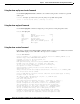
console screen displays a script and system banner similar to the following:
Cisco Internetwork Operating System Software
IOS (tm) 7200 Software (C7200-J-M), 11.3(2)T
Copyright (c) 1986-1998 by cisco Systems, Inc.
Compiled Sun 22-Feb-98 06:00 by Biff
This completes the procedures for connecting input power and powering up the router. This also
completes the procedure for installing the NPE-G1 or NPE-G2 in a Cisco 7200 VXR or
Cisco uBR7246VXR router.