
Installation guide

7-43
Network Processing Engine and Network Services Engine Installation and Configuration
OL-4448-08
Chapter 7 NPE-G1 and NPE-G2 Installation and Configuration Information
Installing the NPE-G1 or NPE-G2
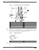
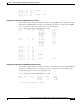
Step 7 Run the +V and –V leads between the two strain-relief studs on the power supply faceplate.
Note A service loop is not required in the lead attached to the grounding lug because this lead is
separate from the +V and –V leads and is secured by two M5 nuts to the M5 receptacles.
Step 8 Replace the strain-relief cover over the +V and –V leads and secure the cover to the strain-relief studs
with the two M4 nuts using the 7-mm wrench or nut driver (or adjustable wrench).
Step 9 Restore current to the –V and +V leads.
Note For the Cisco uBR7200 series routers, each DC-input power supply rating is 14A, 700 volt
ampere (VA).
This product relies on the building’s installation for short-circuit (overcurrent) protection.
Ensure that a listed and certified fuse or circuit breaker, 35A minimum 60 VDC, is used on all
current-carrying conductors. Site wiring and circuit breakers need to be sized to accommodate
the maximum values for safety reasons.
Step 10 Repeat Step 1 through Step 9 if a second power supply is installed.
This completes the steps for reconnecting DC-input power to a Cisco uBR7246 router. Proceed to the
following section, “Powering Up the Router.”
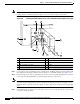
Powering Up the Router
To power up a Cisco 7200 VXR or Cisco uBR7246VXR router that has an installed power supply,
complete the following steps:
Step 1 Check for the following:
–
Each port adapter is inserted in its slot, and its respective port adapter lever is in the locked
position.
–
The network processing engine and the I/O controller or I/O controller blank panel are inserted
in their respective slots, and the captive installation screws are tightened.
–
All network interface cables are connected to the port adapters or I/O controller or NPE-G1 or
NPE-G2 interfaces.
–
Each cable interface line card is inserted in its slot, and its respective captive installation screws
are tightened (Cisco uBR7246VXR only).
–
(Optional) A CompactFlash Disk is installed in the CompactFlash Disk slot in the NPE-G1or
NPE-G2. If you also have an I/O controller installed, you can optionally install a PC Card or
Flash Disk in one of the controller’s PC Card slots.
Note A Flash Disk can be installed in either slot 0 or slot 1 of the I/O controller. A
CompactFlash Disk can be installed only in the CompactFlash Disk slot in the NPE-G1
or NPE-G2.
–
(Optional) A USB Flash memory module or eToken is inserted into a USB port on the NPE-G2.