
Installation guide

7-42
Network Processing Engine and Network Services Engine Installation and Configuration
OL-4448-08
Chapter 7 NPE-G1 and NPE-G2 Installation and Configuration Information
Installing the NPE-G1 or NPE-G2
Note The ground lead for the Cisco uBR7200 series DC-input power supply consists of a two-hole grounding
lug that connects to an M5 grounding receptacle; you do not need to strip this ground lead.
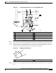
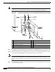
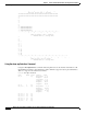
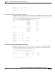
Figure 7-30 Replacing the Strain-Relief Cover on a Cisco uBR7200 Series DC-Input Power Supply
Step 4 Connect the two-hole grounding lug on the grounding lead to the M5 grounding receptacles with the M5
nuts. Tighten the nuts using an 8-mm wrench or nut driver (or adjustable wrench). (See Figure 7-30.)
Step 5 Insert the stripped end of the +V lead all the way into the +V lead receptacle and tighten the receptacle
screw using the 3/16-inch flat-blade screwdriver. Repeat this step for the –V lead.
Note Make sure that the entire stripped end of each lead is inserted all the way into its receptacle. If any
exposed wire at the stripped end of a lead is visible after inserting the lead into its receptacle, remove
the lead from the receptacle, use the wire stripper to cut the stripped end of the lead, and repeat through
Step 5.
Step 6 After tightening the receptacle screw or nuts for the ground, +V, and –V DC-input leads, secure the leads
to the power supply faceplate.
1 Power switch 6 –V lead
2 Power receptacle 7 +V lead
3 Captive installation screw 8 Strain-relief cover
4 M5 grounding receptacles 9 M4 nuts
5 M5 grounding lug
3
5
6
7
8
1 2
9
4
66409