
Installation guide

7-41
Network Processing Engine and Network Services Engine Installation and Configuration
OL-4448-08
Chapter 7 NPE-G1 and NPE-G2 Installation and Configuration Information
Installing the NPE-G1 or NPE-G2
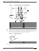
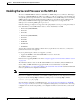
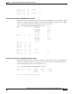
Figure 7-28 Connecting DC-Input Power to a Cisco uBR7246VXR Router
Step 1 At the rear of the router, check that the power switch on the power supply is in the off (O) position.
Step 2 Ensure that no current is running through the –V and +V leads. To ensure that all power is off, locate the
circuit breaker on the panel board that services the DC circuit, switch the circuit breaker to the off
position, and tape the switch handle of the circuit breaker in the off position.
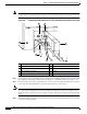
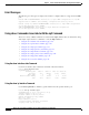
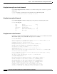
Figure 7-29 Stripping the DC-Input Lines
Step 3 If necessary, use a wire stripper to strip approximately 0.55 inch (14 mm) from the –V, +V, and ground
leads.
1 Power switch 6 –V lead
2 Power receptacle 7 M4 studs
3 Captive installation screw 8 +V lead
4 M5 grounding receptacles 9 Handle
5 M5 grounding lug
66407
3
8
1
2
9
7
5
6
4
1 0.55 in. (14 mm)
57019
1