
Installation guide

7-30
Network Processing Engine and Network Services Engine Installation and Configuration
OL-4448-08
Chapter 7 NPE-G1 and NPE-G2 Installation and Configuration Information
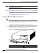
Installing the NPE-G1 or NPE-G2
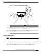
Note The captive installation screws on the NPE-G1 or NPE-G2 must be fastened to allow the
cable-management bracket to provide proper cable support and strain relief. Always ensure that the
captive installation screws are properly tightened.
Note Do not use the cable-management bracket as a handle for inserting and removing the NPE-G1 or
NPE-G2 in the chassis. You must always first unfasten the NPE-G1 or NPE-G2 captive installation
screws and remove the cable-management bracket before removing or inserting the NPE-G1 or NPE-G2
in the chassis.
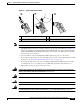
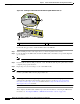
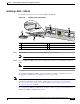
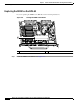
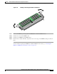
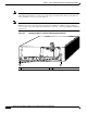
Figure 7-17 Installing the NPE-G1 or NPE-G2 Cable-Management Bracket
.
1 Captive installation screw 2 Captive installation screw
NETWORK PROCESSING ENGINE-300
GIGABIT ETHERNET 0/1
RJ45
GBIC
EN
RX TX
LINK
CONSOLE
AUX
GIGABIT ETHERNET 0/1
RJ45 GBIC
EN
RX TX
LINK
GIGABIT ETHERNET 0/1
RJ45
GBIC
EN
RX TX
LINK
CPU
RESET
COMPACT FLASH
POWER
OK
SLOT
ACTIVE
NETWORK PROCESSING ENGINE - G1
80680
2
1