C H A P T E R 7 NPE-G1 and NPE-G2 Installation and Configuration Information This chapter provides information on installing and configuring the NPE-G1 and NPE-G2 and contains the following sections: Note • Preparing for an Upgrade, page 7-2 • Copying the Configuration File, page 7-4 • Removing the Network Processing Engine, page 7-7 • Installing the NPE-G1 or NPE-G2, page 7-18 • Enabling the Second Processor on the NPE-G1, page 7-45 • Copying the Saved Configuration to NVRAM, page 7-51 • A
Chapter 7 NPE-G1 and NPE-G2 Installation and Configuration Information Preparing for an Upgrade Tip Before you begin any removal or installation procedure, read Chapter 8, “Preparation for Installation.” Also, for the NPE-G1, see the NPE-G1 Read Me First document, at the following URL: http://www.cisco.com/en/US/products/hw/routers/ps341/prod_installation_guide09186a00805e396a.ht ml For the Cisco uBR7200-NPE-G1, see the Cisco uBR7200-NPE-G1 Read Me First document, at the following URL: http://www.cisco.
Chapter 7 NPE-G1 and NPE-G2 Installation and Configuration Information Preparing for an Upgrade Before you install an NPE-G1 or NPE-G2 in an existing router and remove the existing processor and I/O controller, do the following: Step 1 Copy the configuration file from the existing router to a TFTP server, Flash Disk, or PC Card. See the “Copying the Configuration File” section on page 7-4 for details.
Chapter 7 NPE-G1 and NPE-G2 Installation and Configuration Information Copying the Configuration File Copying the Configuration File Caution Before powering down the router to install the NPE-G1 or NPE-G2, you must save the current configuration to a Flash Disk, PC Card, Trivial File Transfer Protocol (TFTP) file server, or PC before you install the NPE-G1 or NPE-G2, or the configuration will be lost and you will have to manually re-enter your configuration.
Chapter 7 NPE-G1 and NPE-G2 Installation and Configuration Information Copying the Configuration File Step 3 Make sure you are at the privileged level of the EXEC command interpreter (check the system prompt for a pound sign [#]). If the system prompt does not have a pound sign (#), enter enable, and then your password. Step 4 Enter the show running-config command to display the router’s running configuration. Ensure that the configuration information is complete and correct.
Chapter 7 NPE-G1 and NPE-G2 Installation and Configuration Information Copying the Configuration File Router# copy startup-config tftp Remote host []? Step 5 Enter the name or IP address of the remote host. In the following example, the name of the remote host is servername: Router# copy startup-config tftp Remote host []? servername Translating "servername"...domain server (10.1.1.1) [OK] Step 6 The EXEC command interpreter prompts you for the name of the file that will contain the configuration.
Chapter 7 NPE-G1 and NPE-G2 Installation and Configuration Information Removing the Network Processing Engine Copying the Configuration File Using a PC Complete the following steps to copy the router’s configuration file to text file on a PC connected to the router’s console port. Step 1 Connect a serial port on the PC to the router’s console port. Start a terminal program on the PC and configure it for the same baud rate, parity, and stop-bits that the console port is using.
Chapter 7 NPE-G1 and NPE-G2 Installation and Configuration Information Removing the Network Processing Engine Ensuring Easy Access to the Router If your Cisco 7200 VXR or Cisco uBR7246VXR router is installed in a standard 19-inch, 4-post or telco-type rack, cables from other equipment in the rack might obstruct access to the rear of the router. Also, rack power strips or other permanent fixtures may obstruct access to the router.
Chapter 7 NPE-G1 and NPE-G2 Installation and Configuration Information Removing the Network Processing Engine Step 1 Facing the rear of the router, place the power switch on the power supply in the off (O) position. Repeat this action if a second power supply is installed in the router. Note Step 2 Caution When powering off the router, wait a minimum of 30 seconds before powering it on again. Observe the following items: • The green OK LED on the power supply turns off. • The fans stop operating.
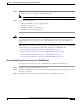
Chapter 7 NPE-G1 and NPE-G2 Installation and Configuration Information Removing the Network Processing Engine Figure 7-1 Disconnecting Power from a Cisco 7200 VXR Router AC-Input Power Supply 1 66415 2 NETWORK PROCESSING ENGINE-300 3 Step 4 4 1 AC-input receptacle 3 Power switch 2 Internal fans 4 AC-input power supply Repeat Step 1 through Step 3 if a second power supply is installed. This completes the procedure for disconnecting AC-input power from a Cisco 7200 VXR router.
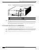
Chapter 7 NPE-G1 and NPE-G2 Installation and Configuration Information Removing the Network Processing Engine Figure 7-2 Disconnecting Power from a Cisco uBR7246VXR AC-Input Power Supply 4 66434 5 1 Step 4 2 3 1 AC-input receptacle 4 Network processing engine 2 Power switch 5 AC-input power supply 3 Handle Repeat Step 1 through Step 3 if a second power supply is installed. This completes the procedure for disconnecting AC-input power from a Cisco uBR7246VXR router.
Chapter 7 NPE-G1 and NPE-G2 Installation and Configuration Information Removing the Network Processing Engine Step 3 Disconnect the –V and +V leads. You can leave the ground cable connected. Step 4 For a Cisco 7200 VXR router, remove the cable tie that secures the –V, +V, and ground leads to the power supply faceplate. Save the cable tie. Note The cable tie that accompanied your Cisco 7200 VXR router DC-input power supply can be removed and replaced on the power supply without the use of a tool.
Chapter 7 NPE-G1 and NPE-G2 Installation and Configuration Information Removing the Network Processing Engine Disconnecting DC-Input Power from a Cisco uBR7246VXR Router To disconnect DC-input power from a Cisco uBR7246VXR router, complete the following steps. Warning Before completing any of the following steps, and to prevent short-circuit or shock hazards, ensure that power is removed from the DC circuit.
Chapter 7 NPE-G1 and NPE-G2 Installation and Configuration Information Removing the Network Processing Engine Figure 7-4 Removing the Strain-Relief Cover from a Cisco uBR7246VXR DC-Input Power Supply 1 2 8 3 9 4 5 6 Step 4 66408 7 1 Power switch 6 –V lead 2 Power receptacle 7 +V lead 3 Captive screw 8 Strain-relief cover 4 M5 grounding receptacles 9 M4 nuts and studs 5 M5 grounding lug Using a 3/16-inch flat-blade screwdriver, loosen the screw below the +V lead receptacle an
Chapter 7 NPE-G1 and NPE-G2 Installation and Configuration Information Removing the Network Processing Engine Figure 7-5 Disconnecting Power from a Cisco uBR7246VXR DC-Input Power Supply 2 1 9 3 4 7 5 Step 5 66406 8 6 1 Power switch 6 –V lead 2 Power receptacle 7 M4 studs 3 DC Power supply 8 +V lead 4 M5 grounding receptacles 9 Handle 5 M5 grounding lug Using an 8-mm wrench or nut driver (or adjustable wrench), loosen and remove the two M5 nuts that secure the two-hole ground
Chapter 7 NPE-G1 and NPE-G2 Installation and Configuration Information Removing the Network Processing Engine Removing the NPE or NSE-1 To remove the NPE or NSE-1 from a Cisco 7200 VXR or Cisco uBR7246VXR router complete the following steps. Note The weight of installed power supplies in your Cisco 7200 VXR or Cisco uBR7246VXR router might make it difficult to remove the network processing engine.
Chapter 7 NPE-G1 and NPE-G2 Installation and Configuration Information Removing the Network Processing Engine Cisco 7200 VXR Router NPE Captive Installation Screws and Handle 66605 Figure 7-6 NETWORK PROCESSING ENGINE-300 1 2 3 4 1 Captive installation screw 3 Network processing engine or network services engine 2 Handle 4 AC-input power supply Step 4 Using a 3/16-inch flat-blade screwdriver, loosen the screws that secure the router to the front mounting strips of the rack.
Chapter 7 NPE-G1 and NPE-G2 Installation and Configuration Information Installing the NPE-G1 or NPE-G2 Installing the NPE-G1 or NPE-G2 To install the NPE-G1 or NPE-G2 in the router, use the following procedures: • Basic Guidelines, page 7-18 • Installing a CompactFlash Disk, page 7-19 • Installing a USB Flash Memory Module or eToken—NPE-G2, page 7-19 • Installing an SFP Module—NPE-G2, page 7-20 • Installing a GBIC—NPE-G1, page 7-23 • Replacing the DIMM on the NPE-G2, page 7-24 • Upgrading th
Chapter 7 NPE-G1 and NPE-G2 Installation and Configuration Information Installing the NPE-G1 or NPE-G2 Installing a CompactFlash Disk Use the following instructions to install the CompactFlash Disk.
Chapter 7 NPE-G1 and NPE-G2 Installation and Configuration Information Installing the NPE-G1 or NPE-G2 Caution Do not remove a USB Flash memory module when a read or write operation to the USB Flash memory module is in progress. The router might reload, or the USB Flash memory module card can be damaged. Note Only Cisco USB Flash memory modules and the Aladdin USB eToken Pro key are supported by Cisco routers.
Chapter 7 NPE-G1 and NPE-G2 Installation and Configuration Information Installing the NPE-G1 or NPE-G2 Figure 7-9 Types of SFP Module Latches 2 3 80755 1 Note 1 Sliding latch 3 2 Swing and slide latch Swing latch The SFP module must be installed before you connect the cables to it. • The SPF module has three types of latches, which are also the removal mechanism. See Figure 7-9.
Chapter 7 NPE-G1 and NPE-G2 Installation and Configuration Information Installing the NPE-G1 or NPE-G2 Figure 7-10 Inserting an SFP Module into the NPE-G2 Gigabit Ethernet Port 0/1 LINK ACTV 1 EN GIGABI T ETHE RNET 0 LINK ACTV /1 GIGABI T ETHE RNET 0 LINK ACTV TX RX RJ45 /2 EN EN 149065 RJ45 2 1 SFP port 0/1 2 SFP module Use the following procedure to install an SFP module in the NPE-G2: Step 1 Attach an ESD-preventive wrist strap between you and an unpainted chassis surface.
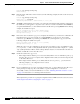
Chapter 7 NPE-G1 and NPE-G2 Installation and Configuration Information Installing the NPE-G1 or NPE-G2 Installing a GBIC—NPE-G1 Use the instructions in this section to install a GBIC in the NPE-G1. Figure 7-11 Installing a GBIC in the NPE-G1 3 ETHER NET 0 /1 4 GIGAB IT ETH ER LINK 5 RX GBIC NET 0 /2 TX RJ45 EN RX GBIC 66774 2 1 Step 1 1 GBIC 4 GBIC port 0/2 2 Alignment groove 5 Plug 3 GBIC port 0/1 Turn the GBIC so the label side is up and the alignment groove is down.
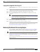
Chapter 7 NPE-G1 and NPE-G2 Installation and Configuration Information Installing the NPE-G1 or NPE-G2 Replacing the DIMM on the NPE-G2 If you are replacing the DIMM on the NPE-G2, use the following instructions. Figure 7-12 Locating the DIMM on the NPE-G2 149472 1 1 Step 1 DIMM Locate the DIMM on the NPE-G2. See Figure 7-12.
Chapter 7 NPE-G1 and NPE-G2 Installation and Configuration Information Installing the NPE-G1 or NPE-G2 Installing or Removing the DIMM on the NPE-G2 149068 Figure 7-13 Step 1 Remove the DIMM by pressing against the DIMM latches until the DIMM releases. Step 2 Gently remove it from the DIMM socket. Step 3 Gently insert a DIMM into the DIMM socket. Step 4 Push the release latches until they slip into the notch on the edge of the DIMM, holding it securely in place.
Chapter 7 NPE-G1 and NPE-G2 Installation and Configuration Information Installing the NPE-G1 or NPE-G2 Upgrading the SDRAM SODIMMs on the NPE-G1 (Optional) If you have purchased an SDRAM memory upgrade for the NPE-G1, replace the SDRAM SODIMMs on the NPE-G1 using the following instructions.
Chapter 7 NPE-G1 and NPE-G2 Installation and Configuration Information Installing the NPE-G1 or NPE-G2 Figure 7-15 Removing or Installing an SDRAM SODIMM 66437 1 1 Step 2 SODIMM Remove the SODIMM you wish to replace by pulling outward on the SODIMM spring latches with your thumbs. The SODIMM springs up to allow you to easily pull it from the socket. Step 3 Remove the SODIMM from the socket.
Chapter 7 NPE-G1 and NPE-G2 Installation and Configuration Information Installing the NPE-G1 or NPE-G2 Caution When inserting the SODIMM, use firm but not excessive pressure. If you damage a socket, you will have to return the NPE-G1 to the factory for repair. Step 4 Gently press on the SODIMM until the SODIMM spring latches snap into place. Step 5 If the SODIMM appears misaligned, carefully remove it and reseat it in the socket.
Chapter 7 NPE-G1 and NPE-G2 Installation and Configuration Information Installing the NPE-G1 or NPE-G2 Step 2 Gently slide the NPE-G1 or NPE-G2 all the way into its chassis slot until you feel the connectors seat with the router midplane. Step 3 Seat the NPE-G1 or NPE-G2 in the router midplane by tightening its captive installation screws with a number 2 Phillips or a 3/16-inch flat-blade screwdriver.
Chapter 7 NPE-G1 and NPE-G2 Installation and Configuration Information Installing the NPE-G1 or NPE-G2 Note The captive installation screws on the NPE-G1 or NPE-G2 must be fastened to allow the cable-management bracket to provide proper cable support and strain relief. Always ensure that the captive installation screws are properly tightened. Note Do not use the cable-management bracket as a handle for inserting and removing the NPE-G1 or NPE-G2 in the chassis.
Chapter 7 NPE-G1 and NPE-G2 Installation and Configuration Information Installing the NPE-G1 or NPE-G2 Figure 7-18 Installing the Cisco uBR7200-NPE-G1 Cable-Management Bracket .
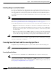
Chapter 7 NPE-G1 and NPE-G2 Installation and Configuration Information Installing the NPE-G1 or NPE-G2 Installing the Rear Cable-Management Brackets with an NPE-G1—Router Front-Mounted H6423 Figure 7-19 1 1 GIGABIT ETHERNET 0/1 GIGABIT ETHERNET 0/1 LINK GIGABIT ETHERNET 0/1 LINK NETWORK PROCESSING ENGINE - G1 LINK CPU RESET EN RX GBIC TX RJ45 EN RX GBIC TX RJ45 SLOT ACTIVE EN RX GBIC TX C O M PA C T F L A S H POWER OK CONSOLE AUX 66749 RJ45 1 Screws Step 1 If the back of t
Chapter 7 NPE-G1 and NPE-G2 Installation and Configuration Information Installing the NPE-G1 or NPE-G2 Installing the Rear Cable-Management Brackets with the NPE-G1 or NPE-G2—Router Rear-Mounted 66750 Figure 7-20 EN 1 GIGABIT ETHERNET 0/1 GIGABIT ETHERNET 0/1 LINK GIGABIT ETHERNET 0/1 LINK NETWORK PROCESSING ENGINE - G1 LINK CPU RESET RJ45 1 EN RX GBIC TX RJ45 EN RX GBIC TX RJ45 1 SLOT ACTIVE EN RX GBIC TX C O M PA C T F L A S H POWER ON CONSOLE AUX Screws Step 1 Align the
Chapter 7 NPE-G1 and NPE-G2 Installation and Configuration Information Installing the NPE-G1 or NPE-G2 You have finished installing the cable-management brackets. Go to the “Reconnecting Input Power and Powering Up the Router” section on page 7-35. Installing the Default Cable-Management Bracket on a Cisco uBR7246VXR Router (Optional) If you are not using the NPE-G1 cable-management bracket, you can alternatively use two cable-management bracket configurations for the Cisco uBR7246VXR router.
Chapter 7 NPE-G1 and NPE-G2 Installation and Configuration Information Installing the NPE-G1 or NPE-G2 Installing the Chassis in a Telco-Type Rack with an Installed Cable-Management Bracket 1 1 2 Rack-mount bracket 93812 Figure 7-23 2 Cable-management bracket Reconnecting Input Power and Powering Up the Router The following procedures explain how to reconnect input power to a Cisco 7200 VXR or Cisco uBR7246VXR router, power up the router, and verify a successful system boot.
Chapter 7 NPE-G1 and NPE-G2 Installation and Configuration Information Installing the NPE-G1 or NPE-G2 Figure 7-24 Connecting AC-Input Power to a Cisco 7200 VXR Router 84398 1 3 2 Step 4 4 5 1 Power switch 4 Cable-retention clip 2 AC power cable 5 Hole for nylon cable tie 3 POWER OK LED Plug the AC power supply cable into the AC power source. Note For Cisco 7200 VXR routers, each AC-input power supply operating at 120 VAC requires a minimum of 5A service.
Chapter 7 NPE-G1 and NPE-G2 Installation and Configuration Information Installing the NPE-G1 or NPE-G2 Reconnecting AC-Input Power to the Cisco uBR7246VXR Router Figure 7-25 Connecting AC-Input Power to a Cisco uBR7246VXR Router 1 6 5 2 3 66422 4 1 Cable-retention clip 4 AC power cable 2 Power receptacle 5 Power switch 3 Captive installation screw 6 Handle To reconnect AC-input power to a Cisco uBR7246VXR router, complete the following steps: Step 1 At the rear of the router, check th
Chapter 7 NPE-G1 and NPE-G2 Installation and Configuration Information Installing the NPE-G1 or NPE-G2 Reconnecting DC-Input Power to the Cisco 7200 VXR Router To reconnect DC-input power to a Cisco 7200 VXR router, complete the following steps. Note The color coding of the DC-input power supply leads depends on the color coding of the DC power source at your site. Typically, green or green and yellow are used for ground.
Chapter 7 NPE-G1 and NPE-G2 Installation and Configuration Information Installing the NPE-G1 or NPE-G2 Figure 7-27 Stripping the DC-Input Lines 57019 1 1 0.55 in. (14 mm) Step 4 For the Cisco 7200 VXR routers, insert the stripped end of the ground lead all the way into the ground lead receptacle on the DC-input power supply and tighten the receptacle screw using a 3/16-inch flat-blade screwdriver.
Chapter 7 NPE-G1 and NPE-G2 Installation and Configuration Information Installing the NPE-G1 or NPE-G2 This completes the steps for reconnecting DC-input power to a Cisco 7200 VXR router. Proceed to the section, “Powering Up the Router” section on page 7-43. Reconnecting DC-Input Power to a Cisco uBR7246VXR Router To reconnect DC-input power to a Cisco uBR7246VXR router, complete the following steps.
Chapter 7 NPE-G1 and NPE-G2 Installation and Configuration Information Installing the NPE-G1 or NPE-G2 Figure 7-28 Connecting DC-Input Power to a Cisco uBR7246VXR Router 1 2 9 3 4 7 66407 8 5 6 1 Power switch 6 –V lead 2 Power receptacle 7 M4 studs 3 Captive installation screw 8 +V lead 4 M5 grounding receptacles 9 Handle 5 M5 grounding lug Step 1 At the rear of the router, check that the power switch on the power supply is in the off (O) position.
Chapter 7 NPE-G1 and NPE-G2 Installation and Configuration Information Installing the NPE-G1 or NPE-G2 Note The ground lead for the Cisco uBR7200 series DC-input power supply consists of a two-hole grounding lug that connects to an M5 grounding receptacle; you do not need to strip this ground lead.
Chapter 7 NPE-G1 and NPE-G2 Installation and Configuration Information Installing the NPE-G1 or NPE-G2 Step 7 Run the +V and –V leads between the two strain-relief studs on the power supply faceplate. Note A service loop is not required in the lead attached to the grounding lug because this lead is separate from the +V and –V leads and is secured by two M5 nuts to the M5 receptacles.
Chapter 7 NPE-G1 and NPE-G2 Installation and Configuration Information Installing the NPE-G1 or NPE-G2 – Each AC-input power cable is connected and secured with the cable-retention clip (AC-input power supplies only). – For a Cisco 7200 VXR router, each DC lead is connected and secured to the power supply faceplate with a cable tie.
Chapter 7 NPE-G1 and NPE-G2 Installation and Configuration Information Enabling the Second Processor on the NPE-G1 Enabling the Second Processor on the NPE-G1 The Cisco 7200VXR NPE-G1 includes a dual-CPU-core BCM 1250 processor. All Cisco IOS images for the Cisco 7200VXR NPE-G1 use CPU-core 0. CPU-core 1 allows acceleration of specific feature sets via separately purchased special software. As of Cisco IOS Release 12.
Chapter 7 NPE-G1 and NPE-G2 Installation and Configuration Information Enabling the Second Processor on the NPE-G1 Error Messages The following error messages are displayed if a feature is configured that is not supported in the MPF path: Router# %MPF-4-IGNOREDFEATURES: Interface Gi0/3: Input "PBR" configurations are not MPF supported and are IGNORED.
Chapter 7 NPE-G1 and NPE-G2 Installation and Configuration Information Enabling the Second Processor on the NPE-G1 Inbound access list is not set Proxy ARP is enabled Local Proxy ARP is disabled Security level is default Split horizon is enabled ICMP redirects are always sent ICMP unreachables are always sent ICMP mask replies are never sent IP fast switching is enabled IP fast switching on the same interface is disabled IP Flow switching is disabled IP CEF switching is enabled IP Feature Fast switching t
Chapter 7 NPE-G1 and NPE-G2 Installation and Configuration Information Enabling the Second Processor on the NPE-G1 0 5 0 5 0 5 0 5 0 5 CPU% per second (last 60 seconds) 3333333333333333333333333333333333333333333333333333333333 3333333333333333333333333333333333333333333333333333333333 100 90 80 70 60 50 40 30 ################# 20 ################# 10 ################# 0....5....1....1....2....2....3....3....4....4....5....5....
Chapter 7 NPE-G1 and NPE-G2 Installation and Configuration Information Enabling the Second Processor on the NPE-G1 Gi0/1.201 Gi0/1.202 Gi0/1.206 Gi0/1.2002 Gi0/1.2004 201 202 206 602 604 up up up up up RX punts 29 RX punts 26114 Using the show mpf interface GigabitEthernet 0/1 Command The following example displays the interface information for GigabitEthernet 1/0, subinterface number 100.
Chapter 7 NPE-G1 and NPE-G2 Installation and Configuration Information Enabling the Second Processor on the NPE-G1 Using the show mpf ip exact-route Command Use the show ip mpf exact-route command to show which routing decision is made for a given IP address pair. hostname: show mpf ip exact-route [vrf vrf_name] src-ip-addr dst-ip-addr 1.1.1.1 -> 192.168.255.255 :Gi2/0/0 (next hop 10.1.255.
Chapter 7 NPE-G1 and NPE-G2 Installation and Configuration Information Copying the Saved Configuration to NVRAM mb2 has a total of 700 bandwidth points. This configuration has oversubscripted the PCI bus and is not a supported configuration. Please refer to the following document "Cisco 7200 Series Port Adaptor Hardware Configuration Guidelines" on CCO , for c7200 bandwidth points oversubscription/usage guidelines.
Chapter 7 NPE-G1 and NPE-G2 Installation and Configuration Information Copying the Saved Configuration to NVRAM You have finished copying and writing the saved configuration file to NVRAM. Copying the Saved Configuration File from the CompactFlash Disk If you have been able to copy the configuration file to the CompactFlash Disk, use the following steps to copy the configuration to the NVRAM on the NPE-G1 or NPE-G2.
Chapter 7 NPE-G1 and NPE-G2 Installation and Configuration Information Copying the Saved Configuration to NVRAM Before configuring the new interfaces on the NPE-G1 or NPE-G2, be prepared with the following information: • Protocols and encapsulations you plan to use on the new interface • Protocol-specific information, such as IP addresses if you will configure the interface for IP routing For complete descriptions of interface commands and the configuration options available for Cisco 7200 VXR-related
Chapter 7 NPE-G1 and NPE-G2 Installation and Configuration Information Auxiliary and Console Port Information Booting Router-confg ..... [timed out] • If the display indicates that the process was successful, proceed to the next step. • If the display indicates that the process failed, verify the name or address of the remote server and the filename, and repeat the preceding steps.
Chapter 7 NPE-G1 and NPE-G2 Installation and Configuration Information Configuring the Native Gigabit Ethernet Interfaces Note The Gigabit Ethernet interfaces on the NPE-G1 and NPE-G2 do not support the Inter-Switch Link (ISL) VLAN encapsulation protocol. We recommends that customers use the IEEE 802.1Q VLAN encapsulation protocol as an alternative. Where an application requires the use of ISL, this can be provided by the Fast Ethernet or Gigabit Ethernet port adapters or I/O controllers.
Chapter 7 NPE-G1 and NPE-G2 Installation and Configuration Information Configuring the Native Gigabit Ethernet Interfaces The following speed/duplex settings are supported: Media Type Speed Duplex ------------------------------------------------------RJ45 10, 100, 1000, auto full, half, auto GBIC(1) 1000, auto(2) full, half, auto ------------------------------------------------------- a.
Chapter 7 NPE-G1 and NPE-G2 Installation and Configuration Information Using show Commands to Check the Installation interface GigabitEthernet0/3 no ip address shutdown duplex auto speed auto media-type rj45 no negotiation auto no cdp enable Note At the very minimum, an interface must be configured with the ip address, media-type, and speed commands before it can be enabled using the no shutdown command. Other interface commands might be needed, depending on the nature of the connected network.
Chapter 7 NPE-G1 and NPE-G2 Installation and Configuration Information Using show Commands to Check the Installation port number (slot/port). The chassis slot number for the I/O controller is always slot 0. Table 7-1 lists the NPE-G1, NPE-G2, the I/O controller models, their corresponding interfaces, and the interface addressing syntax for each interface.
Chapter 7 NPE-G1 and NPE-G2 Installation and Configuration Information Using show Commands to Check the Installation Use the show controllers command to display initialization block information, transmit ring, receive ring, and errors for the interface controllers.
Chapter 7 NPE-G1 and NPE-G2 Installation and Configuration Information Upgrading the Cisco IOS Image and the Boot Helper (Boot Loader) Image 5 minute output rate 0 bits/sec, 0 packets/sec 0 packets input, 0 bytes, 0 no buffer Received 0 broadcasts, 0 runts, 0 giants, 0 throttles 0 input errors, 0 CRC, 0 frame, 0 overrun, 0 ignored 0 watchdog, 0 multicast, 0 pause input 0 input packets with dribble condition detected 0 packets output, 0 bytes, 0 underruns 0 output errors, 0 collisions, 4294967295 interfac
Chapter 7 NPE-G1 and NPE-G2 Installation and Configuration Information Upgrading ROMmon on the NPE-G1 or NPE-G2 Step 3 Copy the boot helper image from the TFTP server to Flash memory as follows: router# copy tftp bootflash: Address or name of remote host []? biff Source filename []? c7200-boot-mz.120-5.S Destination filename [c7200-boot-mz.120-5.S]? Accessing tftp://biff/c7200-boot-mz.120-5.S... Loading c7200-boot-mz.120-5.S from 192.168.254.
Chapter 7 NPE-G1 and NPE-G2 Installation and Configuration Information Upgrading ROMmon on the NPE-G1 or NPE-G2 Using the show rom-monitor Command and rommon CLI showmon Commands Use the show rom-monitor command if you are in Cisco IOS, or the rommon CLI showmon command if you are in ROMmon, to determine which ROMmon images are available.
Chapter 7 NPE-G1 and NPE-G2 Installation and Configuration Information Troubleshooting the Upgrade Copyright (c) 1994-2003 by cisco Systems, Inc. Running new upgrade for first time System Bootstrap, Version 12.2(20031011:151758) [biff] Copyright (c) 1994-2003 by cisco Systems, Inc. ROM:Rebooted by watchdog hard reset C7200 platform with 1048576 Kbytes of main memory Upgrade ROMMON initialized rommon 1 > Note It is advisable to load a known good Cisco IOS image after a ROMmon upgrade.
Chapter 7 NPE-G1 and NPE-G2 Installation and Configuration Information Troubleshooting the Upgrade ROMmon Upgrade Error Messages One if these error message appears when the upgrade has failed or if the upgrade image is corrupted: • ROMmon image is not compatible with the ReadOnly image: Router: upgrade rom-monitor file tftp://00.0.00.0/biff/C7200_NPEG2_RMFUR.srec Loading biff/C7200_NPEG2_RMFUR.srec from 00.0.00.
Chapter 7 NPE-G1 and NPE-G2 Installation and Configuration Information Upgrading FPGA on the NPE-G2 Upgrading FPGA on the NPE-G2 A field-programmable gate array (FPGA) device exists on the NPE-G2. FPGA devices do not exist on other Cisco 7200 series routers network processing engines. FPGA devices are a type of field-programmable devices (FPD) that support separate software upgrades.
Chapter 7 NPE-G1 and NPE-G2 Installation and Configuration Information Fiber Optic Cleaning Information Network Processing Engine and Network Services Engine Installation and Configuration 7-66 OL-4448-08