
Technical data


Chapter 2 Basic Configuration
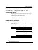
Cisco VG200 Port Numbering
2-2
Software Configuration Guide for the Cisco VG200
78-10322-02
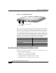
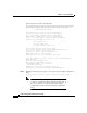
Figure 2-1 Cisco VG200 Analog Ports
Slot 1 contains the voice network module, which can support analog or digital
connections to the Public Switched Telephone Network (PSTN), and which can
hold one or two voice interface cards (VIC). Each VIC, in turn, can provide one
or two ports. During configuration, you refer to each voice port by its numeric
order, starting with zero. Note that the physical ports on a Cisco VG200 gateway
are numbered from right to left, with 1/0/0 identifying the right port on the right
VIC, while 1/1/1 is the left port on the left VIC. The following table lists the
identifiers for each port that can be configured on the Cisco VG200.
Voice/Fax Network Modules and Interface Cards
The analog voice network module and voice interface cards available at this time
for the Cisco VG200 are as follows:
• NM1V One-Slot Voice/Fax Network Module
• NM2V Two-Slot Voice/Fax Network Module
• VIC-1FXS One-Port Voice/Fax Interface Card—FXS
• VIC-2FXS Two-Port Voice/Fax Interface Card—FXS
SEE MANUAL BEFORE INSTALLATION
SERIAL 1
SERIAL 0
CONN CONN
WIC
2A/S
SEE MANUAL BEFORE INSTALLATION
SERIAL 1
SERIAL 0
CONN CONN
WIC
2T
W1
100-240V– 1A
50/60 Hz 47 W
W0
AUX
CONSOLE
ETHERNET 0
ACT
LINK
1/1/1
1/1/0
1/0/1
1/0/0
38135
SEE MANUAL BEFORE INSTALLATION
CONN CONN
WIC
2A/S
SEE MANUAL BEFORE INSTALLATION
CONN CONN
WIC
2A/S
FXS/FX0 Ports
Slot=1/VIC=0/Port=0
Interface type Port numbers (from right to left)
Analog Voice/Fax (FXS, FX0, E&M)
1/0/0, 1/0/1, 1/1/0, 1/1/1
BRI Voice/Fax
1/0/0, 1/1/0
E1/T1 Voice Trunk
1/0, 1/1
Channelized E1/T1 ISDN PRI
1/0, 1/1