C H A P T E R 2 Basic Configuration This chapter describes how to perform basic configuration of your Cisco Voice Gateway 200 (VG200) using the initial configuration dialog and the Cisco IOS command line interface (CLI). Basic configuration includes setting the host name and password and enabling the Fast Ethernet interface.
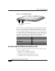
Chapter 2 Basic Configuration Cisco VG200 Port Numbering Figure 2-1 Cisco VG200 Analog Ports SERIAL 1 100-240V– 1A 50/60 Hz 47 W SERIAL 1 WIC CONN 2A/S CONN SEE MANUAL BEFORE INSTALLATION SERIAL 0 WIC CONN 2A/S CONN CONN SEE MANUAL BEFORE INSTALLATION WIC CONN 2A/S SERIAL 0 CONN SEE MANUAL BEFORE INSTALLATION CONN WIC 2T SEE MANUAL BEFORE INSTALLATION W1 W0 LINK ETHERNET 0 ACT 1/1/0 AUX 1/0/1 1/0/0 38135 1/1/1 CONSOLE Slot=1/VIC=0/Port=0 FXS/FX0 Ports Slot 1 contains the voice
Chapter 2 Basic Configuration Cisco VG200 Port Numbering • VIC-1FXO One-Port Voice/Fax Interface Card—FXO • VIC-2FXO One-Port Voice/Fax Interface Card—FXO • VIC-1E/M One-Port Voice/Fax Interface Card—E&M • VIC-2E/M Two-Port Voice/Fax Interface Card—E&M • VIC-1BRI-S/T-TE One-Port BRI Voice/Fax Interface Card • VIC-2BRI-S/T-TE Two-Port BRI Voice/Fax Interface Card Digital T1/E1 Voice Trunk Modules and Interface Cards The T1/E1 voice trunk modules and voice interface cards available at this time
Chapter 2 Basic Configuration Basic Configuration with the Initial Configuration Dialog Channelized E1/T1 ISDN PRI Network Modules The T1/E1 channelized T1 ISDN PRI network modules available at this time for the Cisco VG200 are as follows: • NM-1CT1 1-Port Channelized T1/ISDN PRI Network Module • NM-1CT1-CSU 1-Port Channelized T1/ISDN PRI CSU Network Module • NM-2CT1 2-Port Channelized T1/ISDN PRI Network Module • NM-2CT1-CSU 2-Port Channelized T1/ISDN PRI CSU Network Module • NM-1CE1B 1-Port Ch
Chapter 2 Basic Configuration Basic Configuration with the Initial Configuration Dialog Step 1 Power on the gateway. The power switch is on the rear panel of the gateway, at the lower right corner, near the power cord. Messages will begin to appear in your terminal emulation program window. Caution Do not press any keys on the keyboard until the messages stop.
Chapter 2 Basic Configuration Basic Configuration with the Initial Configuration Dialog The messages look similar to the following: ###################################################################### ###################################################################### ############################################################## [OK] Restricted Rights Legend Use, duplication, or disclosure by the Government is subject to restrictions as set forth in subparagraph (c) of the Commercial Computer Softw
Chapter 2 Basic Configuration Basic Configuration with the Initial Configuration Dialog Step 3 When the following message appears, enter yes to perform basic management setup: Would you like to enter basic management setup? [yes/no]: yes Step 4 Enter the host name for the VG200, as in the following example: Configuring global parameters: Enter host name [Router]: VG200 You must make sure the same entry is used when configuring the Cisco VG200 gateway on Cisco CallManager.
Chapter 2 Basic Configuration Basic Configuration with the Initial Configuration Dialog Step 8 When you see the following prompt, identify the Fast Ethernet interface, which you must configure to use the VG200.
Chapter 2 Basic Configuration Basic Configuration with the Initial Configuration Dialog Step 10 Save the configuration, as follows: The following configuration command script was created: hostname vg200 enable secret 5 $1$6F..$Lc8rqF6Nnos33ARvs9Uu7/ enable password cisco line vty 0 4 password lab snmp-server community public ! no ip routing ! interface FastEthernet0/0 no shutdown full-duplex ip address 192.168.100.1 255.255.255.
Chapter 2 Basic Configuration Voice Interface Configuration with the Intial Configuration Dialog Voice Interface Configuration with the Intial Configuration Dialog From this point on in the initial configuration dialog, the prompts you see vary depending on the network modules in your gateway. The following sections describe the steps for the optional interface modules that require additional configuration using the intitial configuration dialog.
Chapter 2 Basic Configuration Voice Interface Configuration with the Intial Configuration Dialog Table 2-1 ISDN Switch Types (continued) Country ISDN Switch Type North America basic-5ess DescrIption AT&T basic rate switches basic-dms100 NT DMS-100 basic rate switches basic-ni1 National ISDN-1 switches When you reach the following prompt on the System Configuration Dialog, enter an ISDN switch type from Table 2-1: BRI interface needs isdn switch-type to be configured Valid switch types are: [0] n
Chapter 2 Basic Configuration Voice Interface Configuration with the Intial Configuration Dialog The ordering process varies from provider to provider and from country to country. However, here are some general guidelines: • Ask for two channels to be called by one number. • Ask for delivery of calling line identification, also known as caller ID or Automatic Number Identification (ANI).
Chapter 2 Basic Configuration Voice Interface Configuration with the Intial Configuration Dialog Table 2-2 ISDN Provisioning by Switch Type Switch Type Provisioning 5ESS Custom BRI For voice (Use these values only if you have an ISDN telephone connected.
Chapter 2 Basic Configuration Voice Interface Configuration with the Intial Configuration Dialog Table 2-2 ISDN Provisioning by Switch Type (continued) Switch Type Provisioning 5ESS National ISDN (NI-1) BRI Terminal type = A 2 B channels for voice 2 directory numbers assigned by service provider 2 SPIDs required; assigned by service provider Set speed for ISDN calls to 56 kbps outside local exchange Directory number 1 can hunt to directory number 2 DMS-100 BRI 2 B channels for voice 2 directory nu
Chapter 2 Basic Configuration Voice Interface Configuration with the Intial Configuration Dialog If your service provider assigns you SPIDs, you must define these SPIDs on the Cisco VG200.
Chapter 2 Basic Configuration Basic Configuration with the Cisco IOS CLI The following is an example of a E1/T1 PRI mode configuration using the setup command facility: The following framing types are available: esf | sf Enter the framing type [esf]: The following linecode types are available: ami | b8zs Enter the line code type [b8zs]: Enter number of time slots [24]: Do you want to configure Serial1/0:23 interface? [yes]: Basic Configuration with the Cisco IOS CLI The Cisco VG200 runs the Cisco IOS Re
Chapter 2 Basic Configuration Basic Configuration with the Cisco IOS CLI • For a list of command variables, enter the command followed by a space and a question mark, for example: VG200> show ? • To redisplay a command you previously entered, press the up arrow key. You can continue to press the up arrow key for more commands. Command Modes The Cisco IOS interface is divided into different modes. Each command mode permits you to configure different components on your gateway.
Chapter 2 Basic Configuration Basic Configuration with the Cisco IOS CLI Table 2-3 Common Command Modes (continued) Command Mode Interface configuration Dial-peer configuration Timesaver Access Method Gateway Prompt Displayed Exit Method hostname From the global configuration mode, (config-if)# enter the interface The default is router (config-if)# type number command, such as FastEthernet serial 1/0. To exit to global configuration mode, use the exit command.
Chapter 2 Basic Configuration Configuring the Host Name and Password Note You can press Ctrl-Z in any mode to immediately return to privileged EXEC mode (router#), instead of entering exit, which returns you to the previous mode. Disabling a Command or Feature If you want to undo a command you entered or disable a feature, enter the keyword no before most commands; for example, no mgcp.
Chapter 2 Basic Configuration Configuring the Host Name and Password • Connect a terminal to the console port on the gateway. • Power on the gateway. • Wait for the Cisco IOS banner and other information messages to finish displaying.
Chapter 2 Basic Configuration Configuring the Host Name and Password Step 5 Enter line configuration mode by entering the following command from the EXEC mode prompt: VG200(config)# line con 0 When you enter line configuration mode, the prompt changes to router(config-line)#.
Chapter 2 Basic Configuration Configuring the Fast Ethernet Interface This saves the configuration changes to NVRAM so that they are not lost during resets, power cycles, or power outages. Configuring the Fast Ethernet Interface You can use the initial configuration dialog, as described earlier in this chapter, to configure the Fast Ethernet interface on your Cisco VG200 gateway.
Chapter 2 Basic Configuration Configuring the Fast Ethernet Interface Replace ipaddress with the IP address of the Fast Ethernet interface in dotted decimal format. Replace subnetmask with the subnet mask in use on the subnetwork connected to the Fast Ethernet interface.
Chapter 2 Basic Configuration Where to Go Next Where to Go Next At this point you can proceed to the following: • The Cisco IOS software configuration guide and command reference publications for more advanced configuration topics. These publications are available on the Documentation CD-ROM that came with your gateway, on the World Wide Web from Cisco’s home page, or you can order printed copies.