
Specifications


Voice Interface Cards
Multiflex Trunk Interface Cards
17
OL-12847-01
Multiflex Trunk Interface Card LEDs
Multiflex trunk interface cards have three LEDs, which are shown in Figure 97 and Figure 98 and are
described in Table 27.
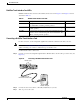
Connecting a Multiflex Trunk Interface Card
For this connection, use the straight-through RJ-48C-to-RJ-48C cable that came with your card.
Note Refer to the Cisco Modular Access Router Specifications for network-end connectors and pinouts of the
cables connecting voice cards. Look under the type of interface card.
Confirm that the router is turned off.
Step 5 Connect one end of the straight-through RJ-48C-to-RJ-48C cable to the T1 or E1 port on the card. (See
Figure 99.)
Figure 99 Connecting a Multiflex Trunk Interface Card
Step 6 Connect the other end to the T1 or E1 wall jack (RJ-48C) at your site.
Step 7 Turn on power to the router.
Table 27 Multiflex Trunk Interface Card LEDs
LED Description Color
LP LED A loopback or line state is detected or is manually set by the
user. This LED is off during normal operation.
Yellow
AL LED A local or remote alarm state exists. This LED is off during
normal operation.
Yellow
CD LED A carrier has been detected, and the internal DSU/CSU in the
interface card is communicating with another DSU/CSU. This
LED is on during normal operation.
Green
VWIC
2MFT-E1-D1
AL
LP
CD
CTRLR E1 1
CTRLR E1 0
SEE
MANUAL
BEFORE
INSTALLATION
Straight-through
RJ-48C-to-RJ-48C cable
RJ-48C wall jack
41202
RJ-48C ports