
User guide


HP Virtual Connect for Cisco Network Administrators (version 4.x)
Document Number: C01386629 Date: January 2014
page 42
addresses with a user-defined range will simply the task. Simply configure port security to allow
the same range of MAC addresses that are manually configured for the user-defined range.
Whether an administrator is configuring port security to allow a certain number of MAC address or to
allow specific MAC addresses, they must configure all Cisco ports assigned to the same vNet (or
Shared Uplink Set) with the same port security settings in order to eliminate communication
problems after a VC uplink failover.
Private VLANs
Private VLANs, or PVLANs, is a Cisco feature that allows switch ports assigned to the same
VLAN to be configured for layer 2 isolation from other switch ports in the same VLAN. The benefit
of this type of feature is enhanced security. For example, an Administrator can assign several
servers to the same VLAN, utilizing the same IP subnet, and only allow the servers to directly
communicate with the default gateway but not with each other.
In the current release of VC firmware, Virtual Connect does not implement support for Private
VLANs within a single vNet. However, an Administrator can achieve complete Layer 2 separation
between server ports by assigning the server ports to separate vNets. Each vNet is a self-contained
Layer 2 network\broadcast domain. Virtual Connect does not internally permit frames to pass
between vNets. This means that a customer can use multiple vNets to isolate servers from each
other within VC.
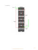
An Administrator can use multiple vNets to extend the function of PVLANs configured on the
upstream Cisco switch. In the example below, two VC vNets and a Cisco Private VLAN have been
used to create two “community” groups and one promiscuous port. All four servers are on the same
VLAN (VLAN 1), however, they are segregated at Layer 2 within VC because they are assigned
to two different vNets (VC_LAN1_A & VC_LAN1_B). These two vNets are uplinked into a
Cisco switch where VLAN 1 has been configured as a Private VLAN. Interface gi0/1 connected to
VC_LAN1_A is an “isolated” port, so it only permits VC_LAN1_A to communicate with the router
port (promiscuous). Also, VC_LAN1_B is connected to interface gi0/3 configured as “isolated” for
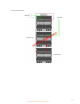
VLAN 1, so it can also only talk to the router. Server 1 and Server 2 can directly communicate
with each other within the VC Domain, however, they both would have to transit the external Cisco
switch in order to communicate with Server 3 and Server 4. As a result, all communication from
Server 1 or 2 to Server 3 or 4 is subject to the PVLAN configuration on the external switch. If
gi0/1 and gi0/3 are isolated ports and gi0/5 is a promiscuous port, then Server 1 and Server 2 can
communicate with each other and with the router, but they cannot communicate with Server 3 or 4.
The same is true for Server 3 and 4 – they can communicate with each other and the router, but
not Servers 1 and 2. Both VC_LAN1_A and VC_LAN1_B function as Community VLANs with
the PVLAN. Note: all servers are on the same VLAN (VLAN 1) and can be assigned IP addresses
from the same subnet.