
User guide


HP Virtual Connect for Cisco Network Administrators (version 4.x)
Document Number: C01386629 Date: January 2014
page 40
Optimizing Virtual Connect Stacking Links
Virtual Connect stacking links provide the physical path between downlinks (server NIC ports) to
VC uplinks. As a result, the fewer VC uplinks a frame has to traverse, the less latency the frame
incurs in reaching the external network. Each VC module a frame must traverse adds
approximately 3.8 microseconds of latency to the frame. Because of the additional latency that each
hop can add, an administrator may wish to add additional stacking links above the recommended
minimum.
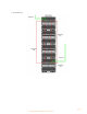
On a per-vNet or per-Shared Uplink Set basis, the VC-Enet module with the active uplink, or
port channel, is the module that all server frames will use to exit the VC domain towards the
external network. For example, if a server NIC port (assigned to vNet1) is connected to VC-Enet
module 2 and the active uplink for vNet1 is connected to VC-Enet module 6, then module 2
will send the frame towards module 8 via the shortest stacking link path. If the modules are
stacked together using stacking links as depicted in the figure above, module 2 will take the path to
module eight via the stacking link to module 7. Module 7 will then use it’s directly connected
internal stacking link to deliver the frame to module 8 and out the uplink towards the external
network. Module 2 could use the longer path via module 1 to module 3 to module 4 to module 8 if it
loses its shorter path through module 7.
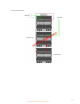
An administrator could purposefully add additional stacking links to provide shorter stacking
link paths between modules. For example using the scenario above, the administrator could add
an additional stacking link between module 2 and module 8. If added, module 2 could send frames
towards the active uplink on module 8 using the directly connected stacking link to module 8.
Purposefully adding additional stacking links is not a common practice since each module’s latency
of 3.8 microseconds is so low.
VC Managed MAC Addresses
One of the many features provided by Virtual Connect is the ability to “manage” the blade server
MAC addresses. Specifically, Virtual Connect ‘manages’ the blade server MAC addresses. Virtual
Connect does not ‘virtualize’ the blade server MAC addresses. Many VC implementers don’t
appreciate the difference between ‘virtualized’ MAC addresses and ‘managed’ MAC addresses.
A ‘virtualized’ MAC address is a MAC address that is not really owned and used by a physical
NIC. Often, a virtualized MAC address is a MAC address that replaces the real MAC address of a
physical NIC without the server’s knowledge. In other words, the server thinks it is
communicating on the network with MAC address X, however, some device is replacing real
MAC address X with a virtual MAC address Y. Many of the benefits of MAC address management
are lost in this type of implementation.
A ‘managed’ MAC address is a MAC address that really is owned and used by a physical NIC. The
server has simply been assigned, by the administrator, to use a specific MAC address on a specific
physical NIC port. This managed MAC address, for all intents and purposes, appears to the server as
the MAC address that was burned into the physical NIC at the factory.
The benefits of VC Managed MAC addresses are:
•
WYSIWYG - What You See (on the server) Is What You Get (on the network)
There is no discrepancy between what the server thinks its MAC address is and what the
external network sees as the server’s MAC address. This dramatically reduces the