
User guide


HP Virtual Connect for Cisco Network Administrators (version 4.x)
Document Number: C01386629 Date: January 2014
page 39
for the associated VMs. Even though vSwitch 1 is redundantly connected to the Data Center LAN,
no loops are formed. In addition, Spanning Tree is not needed between the ESX server and the
Data Center LAN to prevent the loop. Instead, the NIC bonding technology on the ESX host
prevents loops on the network by only allowing one logical path (single NIC port or single channel
group\port trunk) to be active at one time. In comparison, VC uplinks prevent loops in the same
manner. In other words, on a per Virtual Connect network (vNet) basis, each vNet prevents loops
on the Data Center LAN by only allowing one active logical path at a time.
The behavior of the VC uplink ports associated with a vNet can be compared to the NIC ports
associated with a vSwitch. In both cases, Spanning Tree is not needed to prevent loops on the Data
Center LAN. Instead, in both cases “port bonding” technology is used to only allow a single active
logical path at any given time.
Stacking Virtual Connect Ethernet Modules
Virtual Connect can be configured by an Administrator to allow any VC uplink on any VC
Ethernet module to provide external connectivity for any server downlink. VC can also be
configured to allow connectivity between any set of server downlinks on any VC Ethernet module.
Virtual Connect provides this flexible connectivity through the use of ‘stacking links’ between VC
Ethernet modules.
Stacking links allow all VC Ethernet modules in the VC Domain to be configured as, and operate as,
a single device (except for port channeling). Stacking links are to a group of VC Ethernet modules
what the PCI bus is for a team of server NICs – a common communication path allowing all devices
to work together as one.
When any two Virtual Connect Ethernet modules from the same VC domain are directly connected
together using 1 Gb or 10 Gb ports, the two modules automatically negotiate, using LLDP, the link
as a stacking link. No manual configuration is required to make an uplink a stacking link.
Simply connecting two VC uplinks together is all that is required.
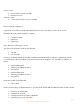
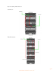
In the figure below, the green horizontal lines represent the internal stacking links that exist
between horizontally-adjacent VC modules by default. The orange vertical lines represent the
external stacking links that HP recommends customer install using 10 Gb or 1 Gb ports. The
minimum recommendations below provide stacking link redundancy for each VC Ethernet module.
Note:
Stacking links are required for all Virtual Connect Ethernet modules in the same Virtual Connect
Domain.