
User guide


HP Virtual Connect for Cisco Network Administrators (version 4.x)
Document Number: C01386629 Date: January 2014
page 28
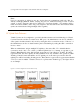
default. In other words, the vNet keeps all frames within the same layer 2 domain (vNet), however, VC
allows the frames to carry different VLAN tags from the external network all the way to the server NIC
ports and vice versa. See VC Uplink 2 in the figure below. When VC uplink ports are assigned to a single
vNet and connected to an external switch port in access mode, the VC uplink and vNet operate in access
mode only carries untagged frames for a single VLAN (the access VLAN on the switch). See VC Uplink 1
in the figure below. In other words, depending on the configuration of the external switch port, a single
vNet could represent a single VLAN or a single vNet could represent multiple VLANs.
Figure 16. VLAN Tagging Examples
(see Appendix A for a description of the elements in the above diagram)
Explanation of the Figure Above:
VC Uplink 3 is assigned to a Shared Uplink Set (SUS) and is tagged with VLANs 2 thru 4.
The external switch port is a trunk port carrying VLANs 2 thru 4
VLAN 2 is represented by vNet-PROD2-A, VLAN 3 is represented by vNet-PROD3,
and VLAN 4 is represented by vNet-PROD4.
VC Uplink 2 is assigned to vNet_ESX and is operating in 802.1Q tunneling mode.
The external switch port is a trunk port carrying VLANs 2 thru 4.
vNet_ESX is a single vNet that represents VLANs 2 thru 4.
VC Uplink 1 is assigned to vNet-PROD2-B and is operating in access mode.
The external switch port is an access port assigned to VLAN 2.
vNet-PROD2-B represents a vNet operating in ‘acccess mode’ for external VLAN 2.
• NIC 1 on both Server 1 and Server 2 have VLAN tagging configured on the server. On