
User guide


HP Virtual Connect for Cisco Network Administrators (version 4.x)
Document Number: C01386629 Date: January 2014
page 24
“mode passive”.
There are four types of scenarios for port trunking\channeling with Virtual Connect Uplink
Ports:
Same VC Module, Same External Switch, Same Port Channel Group
When VC uplinks from the same physical VC-Enet module are assigned to the same vNet (or Shared
Uplink Set) and are connected to ports on the same external Cisco switch that are assigned to the
same port channel group and have the LACP protocol enabled, then VC will automatically form a
single port channel.
Same VC Module, Same External Switch, Different Port Channel Groups
When VC uplinks from the same physical VC-Enet module are assigned to the same vNet (or Shared
Uplink Set) and are connected to ports on the same external Cisco switch that are
assigned to different port channel groups and have the LACP protocol enabled, then VC
may automatically form more than one port channel.
Same VC Module, Different External Switches
When VC uplinks from the same physical VC-Enet module are assigned to the same vNet (or Shared
Uplink Set) and are connected to ports on different external Cisco switches that are
assigned to port channel groups and have the LACP protocol enabled, then VC may
automatically form more than one port channel.
Different VC Module, Same or Different External Switches
When VC uplinks from different physical VC-Enet modules are assigned to the same vNet (or Shared
Uplink Set) and are connected to ports on the same (or different) external Cisco
switch that are assigned to a port channel group and have the LACP protocol enabled, then VC
may automatically form more than one port channel.
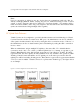
As described above, VC’s default behavior (connection mode ‘auto’) for a vNet is to attempt to
negotiate a port channel (EtherChannel) using 802.3ad Link Aggregation Control Protocol (LACP). If
LACP negotiation is successful for one or more sets of VC uplink ports, a port channel is
formed between the VC Ethernet module and the external switch. A vNet may form more than one
port channel with an external switch or switches. Each port channel behaves as a single logical
path. Like in the previous section describing simple fault tolerance, a vNet can only have one
active logical path at any given time. As such, a vNet with multiple port channels will only use
one port channel as the active logical path and all other port channels in the same vNet will be in
standby mode. See the figure below as an example.
Figure 15. A vNet Utilizing Port Channeling for Load Balancing and Fault Tolerance