
Installation guide

5-2
Cisco Network Convergence System 6000 Series Routers Hardware Installation Guide
Chapter 5 Installing Route Processor Cards, Line Cards, and Fabric Cards
About Installing Cards and Associated Components
• Avoid contact between a card and clothing. The wrist strap protects the board from only ESD voltage
on the body; ESD voltage on clothing can still cause damage.
• Be careful not to lay any tools on the aluminum honeycomb panel, or insert your fingers into the
panel.
Guidelines for Installing and Removing a Card
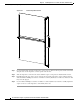
• Every card has a label (with an arrow) on its faceplate showing which side is up for installation.
• Every FC, LC, and RP card has a key mounted on the board that matches a corresponding slot on
the chassis side (top of each card slot). This key-slot mechanism prevents a card from being inserted
into the wrong, non-matching card slot. It also prevents a card from being inserted upside down.
When a card is inserted into the wrong card slot or upside down, the key will get blocked against the
chassis card guide and not slide though the slot. When the key gets blocked, remove the card and
find the correct card slot.
Note RP card faceplates and the card slots on the LCC for RP cards are labeled with the square
symbol. FC faceplates and the card slots on the LCC for FCs cards are labeled with the circle.
symbol.
• Online insertion and removal (OIR) is supported, enabling you to install a card while the LCC is
operating. OIR removes power to a specific slot before the card is replaced. The power remains on
for all other card slots.
OIR is seamless to users on the network, maintains all routing information, and ensures session
preservation. We recommend that you perform a graceful shutdown to shut down a fabric card prior
to removing it from the LCC. See Steps for OIR Fabric Card Removal, page 5-3.
• When installing a fabric card, your must first push the OIR button on both the upper and lower
ejectors for the mechanical latch to be released.
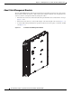
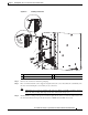
• The different cards in the LCC are all attached to the chassis itself using a pair of ejector levers and
captive screws. The two ejector levers release the card from its midplane connector. The exact
locations of the ejector levers and captive screws can vary slightly from card to card, but are
generally in the same locations: on the upper and bottom ends of the faceplate.
• When you remove a card, always use the ejector levers first to ensure that the connector pins
disconnect from the midplane in the sequence expected by the chassis.
• The chassis is shipped with all card slots containing either impedance carriers or a plastic cover to
help maintain chassis stiffness and prevent any damage to the chassis during shipment.
• Any unused card slots that are uncovered would allow air used for chassis cooling to escape.
Therefore, to ensure proper air flow and maintain system EMC and safety compliance, any unused
LC slots must contain impedance carriers, and all FCs and RP cards must remain installed in their
card slots.
• Fully insert all FCs and RP cards into the chassis before tightening their captive screws.
• For information about the slot numbers, see the “Slot Numbers–Front and Rear Side” section on
page 2-5.