CH A P T E R 5 Installing Route Processor Cards, Line Cards, and Fabric Cards This chapter provides instructions on how to install cards and their associated components in the Cisco NCS 6000 Line Card Chassis (LCC).
Chapter 5 Installing Route Processor Cards, Line Cards, and Fabric Cards About Installing Cards and Associated Components • Avoid contact between a card and clothing. The wrist strap protects the board from only ESD voltage on the body; ESD voltage on clothing can still cause damage. • Be careful not to lay any tools on the aluminum honeycomb panel, or insert your fingers into the panel.
Chapter 5 Installing Route Processor Cards, Line Cards, and Fabric Cards About Installing Cards and Associated Components Caution The chassis may indicate a hardware failure if you do not follow proper procedures. Remove or install only one card at a time. Allow at least 15 seconds for the chassis to complete its tasks before removing or installing another card. Steps for OIR Fabric Card Removal Follow these steps to perform a graceful OIR on the fabric card by using the Cisco IOS XR shutdown command.
Chapter 5 Installing Route Processor Cards, Line Cards, and Fabric Cards About Installing Cards and Associated Components About Cable Management Brackets The Cisco NCS 6008 LCC has cable management features for both the front and rear sides of the chassis. These features organize the interface cables entering and exiting the different cards, keeping them out of the way and free of sharp bends that may damage the cables.
Chapter 5 Installing Route Processor Cards, Line Cards, and Fabric Cards Installing and Removing an Impedance Carrier Installing and Removing an Impedance Carrier The chassis ships with impedance carriers installed in the LC slots. • Installing an Impedance Carrier, page 5-5 • Removing an Impedance Carrier, page 5-7 Installing an Impedance Carrier This section describes how to install an impedance carrier in the Cisco NCS 6008 LCC.
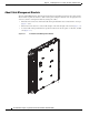
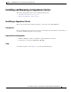
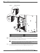
Chapter 5 Installing Route Processor Cards, Line Cards, and Fabric Cards Installing and Removing an Impedance Carrier LC Slot Impedance Carrier 122147 Figure 5-2 Step 1 Use both hands while inserting an impedance carrier. Use one hand on the faceplate and the other hand along the base of the impedance carrier to guide it into the slot. Step 2 Slide the impedance carrier into the chassis until the captive screw plates are flush with the chassis.
Chapter 5 Installing Route Processor Cards, Line Cards, and Fabric Cards Installing a Route Processor Card Removing an Impedance Carrier Prerequisites Before performing this task, open the cosmetic doors, if installed. Required Tools and Equipment • Number-2 Phillips screwdriver or number-2 common (flat-head) screwdriver Steps To remove an impedance carrier (Figure 5-2), perform the following steps: Step 1 Identify the impedance carrier to be removed from the card cage.
Chapter 5 Installing Route Processor Cards, Line Cards, and Fabric Cards Installing a Route Processor Card Prerequisites Before performing this task, open the cosmetic doors, if installed. The RP cards are hot-swappable. Caution Install one RP card at a time. Allow at least 15 seconds for the chassis to complete its tasks before installing another RP card. The chassis may indicate a hardware failure if you do not follow proper procedures.
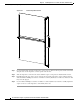
Installing Route Processor Cards, Line Cards, and Fabric Cards Installing a Route Processor Card Figure 5-3 Installing an RP Card 3 2 1 304061 Chapter 5 1 Direction of insertion 2 Ejector lever 3 Captive screw Step 2 Remove the card from its antistatic packaging. Step 3 Place one hand under the card to support and guide it into the correct slot. Slide the card halfway into the slot. Avoid touching the card circuitry or any connectors.
Chapter 5 Installing Route Processor Cards, Line Cards, and Fabric Cards Installing a Route Processor Card Step 5 Carefully slide the RP into the slot until the ejector levers meet the edges of the card cage, and then stop when the ejector lever hooks catch the card cage. If they do not catch, try reinserting the RP until the ejector lever hooks are fully latched.
Installing Route Processor Cards, Line Cards, and Fabric Cards Installing a Route Processor Card Figure 5-4 RP Card Front Panel 1 2 3 4 5 6 7 8 9 10 11 12 13 304080 Chapter 5 1 Status LED—Card status indicator 8 IEEE 1588 Ethernet port 2 Attention LED 9 SYNC0 (BITS/J.211) port 3 Expansion Ethernet ports 10 SYNC1 (BITS/J.
Chapter 5 Installing Route Processor Cards, Line Cards, and Fabric Cards Installing a Route Processor Card Troubleshooting the RP Card Use the Status LED, located on the faceplate of the RP card, to verify the correct installation of the card: Note • When the card is properly installed and no faults are detected, the card status LED turns green. • When the card status LED is solid yellow, either software initialization is in progress during bootup or a fault exists on the board.
Chapter 5 Installing Route Processor Cards, Line Cards, and Fabric Cards Installing Fabric Cards Installing Fabric Cards • Installing a NC6-FC Fabric Card, page 5-13 • Verifying the Installation of a NC6-FC Fabric Card, page 5-16 • About Line Cards, page 5-22 Installing a NC6-FC Fabric Card Prerequisites Before performing this task, open the cosmetic doors, if installed.
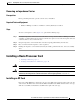
Chapter 5 Installing Route Processor Cards, Line Cards, and Fabric Cards Installing Fabric Cards Figure 5-5 Installing a Fabric Card 3 2 347729 1 1 Ejector lever 2 OIR button 3 Captive screw Step 1 Attach the ESD-preventive wrist strap to your wrist and connect its leash to one of the two ESD jacks on the rear side of the chassis (Figure 2-4). You can also connect the ESD-preventive wrist strap leash to any bare metal surface on the chassis.
Chapter 5 Installing Route Processor Cards, Line Cards, and Fabric Cards Installing Fabric Cards Step 6 Carefully slide the FC into the slot until the ejector levers meet the edges of the card cage, and then stop when the ejector lever hooks catch the card cage. If they do not catch, try reinserting the FC until the ejector lever hooks are fully latched.
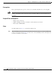
Chapter 5 Installing Route Processor Cards, Line Cards, and Fabric Cards Installing Fabric Cards Verifying the Installation of a NC6-FC Fabric Card Figure 5-6 NC6-FC Front Panel 1 Status LED 3 32 CXP ports (left side 0 through 15, right side LEDs 16 though 31) 2 Attention LED 4 32 CXP port LEDs (one per port) Cisco Network Convergence System 6000 Series Routers Hardware Installation Guide 5-16
Chapter 5 Installing Route Processor Cards, Line Cards, and Fabric Cards Installing Fabric Cards Fabric Card LEDs Table 1 describes the LED indicators for the FCs. • The Status LED and Attention LED indicate the status of the S2 fabric card. Each LED is a bi-color green and yellow LED. • The 32 CXP LEDs indicate the status of the CXP links. Each LED is a bi-color red and green LED. Note that each FC slot must be configured as a fabric instance for the CXP LED to light up.
Chapter 5 Installing Route Processor Cards, Line Cards, and Fabric Cards Installing Fabric Cards Installing an S13 MC Fabric Card This section describes how to install an S13 Multi-Chassis (MC) fabric card in a Cisco NCS 6000 LCC for multi-chassis configurations. Prerequisites • Shut down the fabric plane (S13 slot number) if configured, to avoid traffic loss. The following example shows how to shut down plane X (where X is in the range of 0 to 5).
Chapter 5 Installing Route Processor Cards, Line Cards, and Fabric Cards Installing Fabric Cards Figure 5-7 1 Installing an S13 MC FC in a Cisco NCS 6008 LCC 3 Ejector lever Captive screw 2 OIR buttons (top and bottom of faceplate) Step 5 Place one hand under the card to support and position the card for insertion into the card cage slot. Avoid touching the card circuitry or any connectors. Note Alignment grooves exist on each slot in the card cage.
Chapter 5 Installing Route Processor Cards, Line Cards, and Fabric Cards Installing Fabric Cards Step 6 If the ejector levers are locked in place, press the OIR buttons on the top and bottom of the card faceplate to release the ejectors. Step 7 Carefully slide the card into the slot until the ejector levers meet the edges of the card cage, and then stop when the ejector lever hooks catch the card cage. If they do not catch, try reinserting the card until the ejector lever hooks are fully latched.
Chapter 5 Installing Route Processor Cards, Line Cards, and Fabric Cards Installing Fabric Cards Verifying the Installation of an S13 MC Fabric Card This section describes how to verify that an S13 MC FC card is properly installed and is working correctly in the Cisco NCS 6000 LCC. Use the Status LED, located on the faceplate of the card to verify the correct installation of the card. Figure 5-8 shows the front panel of the card. Table 2 describes the LED indicators and their meanings.
Chapter 5 Installing Route Processor Cards, Line Cards, and Fabric Cards About Line Cards S13 MC Fabric Card LEDs Table 2 describes the LED indicators for the S13 MC FC. • The Status LED and Attention LED indicate the status of the S13 MC fabric card. Each is a bi-color green and yellow LED. • The16 CXP LEDs indicate the status of the CXP links. Each is a bi-color red and green LED.
Installing Route Processor Cards, Line Cards, and Fabric Cards About Line Cards Figure 5-9 10-Port 100Gbps CPAK LC Front Panel 1 2 3 3 303452 Chapter 5 1 Status LED 2 Attention LED 3 Port LEDs (one LED on each port) Cisco Network Convergence System 6000 Series Routers Hardware Installation Guide 5-23
Chapter 5 Installing Route Processor Cards, Line Cards, and Fabric Cards About Line Cards Table 3 describes the LEDs for the 10-port 100Gbps CPAK LC. Table 3 10-Port 100Gbps CPAK LC LED Descriptions LED State Description Status Green The LC is properly seated and operating correctly. Yellow The LC has one or more errors detected. Off No power is applied to the LC. Blue The card needs attention. Off The card does not need attention. Green The link is up (including internal loopback).
Installing Route Processor Cards, Line Cards, and Fabric Cards About Line Cards Figure 5-10 10-Port 100Gbps CXP LC Front Panel 1 2 3 3 303451 Chapter 5 1 Status LED 2 Attention LED 3 Port LEDs (one LED on each port) Cisco Network Convergence System 6000 Series Routers Hardware Installation Guide 5-25
Chapter 5 Installing Route Processor Cards, Line Cards, and Fabric Cards About Line Cards Table 4 describes the LEDs for the 10-port 100Gbps CXP LC. Table 4 10-Port 100Gbps CXP LC LED Descriptions LED State Description Status Green The LC is properly seated and operating correctly. Yellow The LC has one or more errors detected. Off No power is applied to the LC. Blue The card needs attention. Off The card does not need attention. Green The link is up (including internal loopback).
Chapter 5 Installing Route Processor Cards, Line Cards, and Fabric Cards About Line Cards 60-Port 10Gbps Line Card with SFP+ Optics Module The 60-port 10Gbps SFP+ LC (Lean Core [NC6-60X10GE-L-S] and Multi-Service Core [NC6-60X10GE-M-S]) has: • 60 ports that each accept a SFP+ optics module • Attention LED • Status LED • Port LEDs, one on each port Figure 5-11 shows the front panel of the 60-port 10Gbps SFP+ LC.
Chapter 5 Installing Route Processor Cards, Line Cards, and Fabric Cards About Line Cards Figure 5-11 60-Port 10Gbps SFP+ LC Front Panel 1 2 3 390402 3 1 Status LED 2 Attention LED 3 Port LEDs (one LED on each port) Cisco Network Convergence System 6000 Series Routers Hardware Installation Guide 5-28
Chapter 5 Installing Route Processor Cards, Line Cards, and Fabric Cards About Line Cards Table 5-5 describes the LEDs for the 60-port 10Gbps SFP+ LC. Table 5-5 60-Port 10Gbps SFP+ LC LED Descriptions LED State Description Status Green The LC is properly seated and operating correctly. Yellow The LC has one or more errors detected. Off No power is applied to the LC. Blue The card needs attention. Off The card does not need attention. Green The link is up (including internal loopback).
Chapter 5 Installing Route Processor Cards, Line Cards, and Fabric Cards Installing and Removing a Line Card Installing and Removing a Line Card • Installing a Line Card, page 5-30 • Verifying the Installation of a Line Card, page 5-32 • Removing a Line Card, page 5-33 Installing a Line Card Prerequisites Before performing this task, open the cosmetic doors, if installed. Caution Remove or install only one LC at a time.
Chapter 5 Installing Route Processor Cards, Line Cards, and Fabric Cards Installing and Removing a Line Card Figure 5-12 Installing a LC 3 2 1 1 Direction of insertion 2 Ejector lever 3 Captive screw Step 1 Attach the ESD-preventive wrist strap to your wrist and connect its leash to the ESD connection socket on the front side of the chassis (Figure 2-4). You can also connect the ESD-preventive wrist strap leash to any bare metal surface on the chassis.
Chapter 5 Installing Route Processor Cards, Line Cards, and Fabric Cards Installing and Removing a Line Card Step 3 Remove the LC from the antistatic bag. Step 4 Use both hands while inserting a LC. Use one hand on the faceplate and the other hand along the base of the LC to guide it into a slot. Caution To prevent ESD damage, handle a LC by its ejector levers or the LC carrier edges only. Do not touch any of the electrical components, pins, or circuitry.
Chapter 5 Installing Route Processor Cards, Line Cards, and Fabric Cards Installing and Removing a Line Card Removing a Line Card Warning Class 1 Laser Product. Statement 113 Warning Because invisible radiation may be emitted from the aperture of the port when no fiber cable is connected, avoid exposure to radiation and do not stare into open apertures.
Chapter 5 Installing Route Processor Cards, Line Cards, and Fabric Cards Installing and Removing a Line Card Figure 5-13 Removing a LC 1 2 304060 3 1 Captive screw 2 Ejector lever 3 Direction of removal Step 1 Attach the ESD-preventive wrist strap to your wrist and connect its leash to the ESD connection socket on the front side of the chassis (Figure 2-4). You can also connect the ESD-preventive wrist strap leash to any bare metal surface on the chassis.
Chapter 5 Installing Route Processor Cards, Line Cards, and Fabric Cards Installing and Removing a Line Card Step 5 Warning Touching only the metal card carrier, slide the card from the slot and place it directly into an antistatic sack or other ESD-preventive container. Because invisible laser radiation may be emitted from the aperture of the port when no cable is connected, avoid exposure to laser radiation and do not stare into open apertures.
Chapter 5 Installing Route Processor Cards, Line Cards, and Fabric Cards Installing and Removing a Line Card Cisco Network Convergence System 6000 Series Routers Hardware Installation Guide 5-36