
Installation Guide

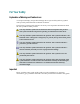
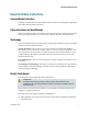
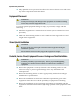
Table Of Contents
- Important Safety Instructions
- Introducing the Addressable Multimedia Stretch Tap
- Introduction to This Document
- Who Should Use This Document
- Qualified Personnel
- Scope
- Document Version
- Installing the Tap
- Overview
- Tools and Torque Specifications
- Preparing for Installation
- Removing the Faceplate
- Installing the Stretch Tap on a Strand
- Installing the Stretch Tap in a Pedestal
- Installing Optional Modules
- Installing the Tiering Filter Module
- Installing the Reverse Conditioning Pad
- Mounting the Faceplate
- Connecting Coax Drop Cables
- Replacing the Local Oscillator Module
- Replacing the Power Supply
- Customer Support Information
- If You Have Questions
- Appendix A Technical Information
- Glossary
- A
- ac, AC
- AC/RF byass switch
- addressable
- aerial mount
- amplifier
- AMST
- attenuation
- attenuator
- ATX
- bit
- broadband
- CATV
- dB
- DC
- dc, DC
- DC/EQ
- decibel
- directional coupler (DC) module
- drop amplifier
- drop cable
- equalization
- equalizer
- F-connector
- FCC
- forward path
- frequency
- FSK
- ft-lb
- GHz
- GND
- headend
- HFC
- Hz
- in-lb
- ingress
- LCSI
- LED
- LO
- MHz
- MST
- MTS
- N-m
- passive
- PCB
- pedestal mount
- PTC
- PWB
- reverse path
- RF
- RMA
- SCTE
- splitter
- strand mount
- tap
- tilt
- torque
- trap
- UL
- V
- V AC
- V DC
- W
- Index
Contents
iv 78-4002497-01 Rev F
Installing the Reverse Conditioning Pad ............................................................................ 32
To Install the Reverse Conditioning Pad ............................................................... 32
Mounting the Faceplate ........................................................................................................ 33
Upgrading the Faceplate .......................................................................................... 33
To Mount the Faceplate ........................................................................................... 33
Connecting Coax Drop Cables ............................................................................................. 36
Bar Code Labels......................................................................................................... 36
Replacing the Local Oscillator Module ............................................................................... 37
To Replace the LO Module ...................................................................................... 37
Replacing the Power Supply ................................................................................................ 38
To Replace the Power Supply ................................................................................. 38
Chapter 3 Customer Support Information 40
Appendix A Technical Information 41
Specifications .......................................................................................................................... 42
Dimensions ................................................................................................................ 42
Electrical Specifications ............................................................................................ 42
AC/RF Bypass Switch Performance ...................................................................... 42
Standards Compliance ............................................................................................. 43
Tap Part Numbers .................................................................................................................. 44
Optional Modules ..................................................................................................... 44
Product Ordering Matrix ......................................................................................... 46
Glossary 49
Index 57