
Installation Guide
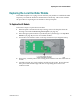
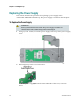
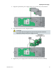
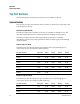
Table Of Contents
- Important Safety Instructions
- Introducing the Addressable Multimedia Stretch Tap
- Introduction to This Document
- Who Should Use This Document
- Qualified Personnel
- Scope
- Document Version
- Installing the Tap
- Overview
- Tools and Torque Specifications
- Preparing for Installation
- Removing the Faceplate
- Installing the Stretch Tap on a Strand
- Installing the Stretch Tap in a Pedestal
- Installing Optional Modules
- Installing the Tiering Filter Module
- Installing the Reverse Conditioning Pad
- Mounting the Faceplate
- Connecting Coax Drop Cables
- Replacing the Local Oscillator Module
- Replacing the Power Supply
- Customer Support Information
- If You Have Questions
- Appendix A Technical Information
- Glossary
- A
- ac, AC
- AC/RF byass switch
- addressable
- aerial mount
- amplifier
- AMST
- attenuation
- attenuator
- ATX
- bit
- broadband
- CATV
- dB
- DC
- dc, DC
- DC/EQ
- decibel
- directional coupler (DC) module
- drop amplifier
- drop cable
- equalization
- equalizer
- F-connector
- FCC
- forward path
- frequency
- FSK
- ft-lb
- GHz
- GND
- headend
- HFC
- Hz
- in-lb
- ingress
- LCSI
- LED
- LO
- MHz
- MST
- MTS
- N-m
- passive
- PCB
- pedestal mount
- PTC
- PWB
- reverse path
- RF
- RMA
- SCTE
- splitter
- strand mount
- tap
- tilt
- torque
- trap
- UL
- V
- V AC
- V DC
- W
- Index
Replacing the Local Oscillator Module
78-4002497-01 Rev F 37
Replacing the Local Oscillator Module
The AMST faceplate uses a plug-in local oscillator (LO) module to establish the FSK
frequency on which the headend communicates with the tap. This section outlines
the procedure for replacing the LO module in the tap faceplate.
To Replace the LO Module
Follow these steps to replace the LO module.
1 If the faceplate is mounted in the tap housing, remove the faceplate from the
housing as described in Removing the Faceplate (on page 19).
2 Select the appropriate module as specified by the system design. See Tap Part
Numbers (on page 44) for a list of available modules.
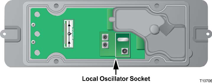
3 Locate the local oscillator socket on the tap circuit board (see diagram below).
4 If necessary, carefully remove the existing local oscillator from the socket and set
it aside.
5 Carefully plug the new local oscillator module into the socket. Be sure that all
three pins on the module align with the corresponding holes in the local
oscillator socket.