
Installation Guide
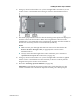
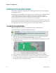
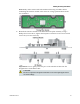
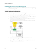
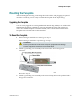
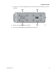
Table Of Contents
- Important Safety Instructions
- Introducing the Addressable Multimedia Stretch Tap
- Introduction to This Document
- Who Should Use This Document
- Qualified Personnel
- Scope
- Document Version
- Installing the Tap
- Overview
- Tools and Torque Specifications
- Preparing for Installation
- Removing the Faceplate
- Installing the Stretch Tap on a Strand
- Installing the Stretch Tap in a Pedestal
- Installing Optional Modules
- Installing the Tiering Filter Module
- Installing the Reverse Conditioning Pad
- Mounting the Faceplate
- Connecting Coax Drop Cables
- Replacing the Local Oscillator Module
- Replacing the Power Supply
- Customer Support Information
- If You Have Questions
- Appendix A Technical Information
- Glossary
- A
- ac, AC
- AC/RF byass switch
- addressable
- aerial mount
- amplifier
- AMST
- attenuation
- attenuator
- ATX
- bit
- broadband
- CATV
- dB
- DC
- dc, DC
- DC/EQ
- decibel
- directional coupler (DC) module
- drop amplifier
- drop cable
- equalization
- equalizer
- F-connector
- FCC
- forward path
- frequency
- FSK
- ft-lb
- GHz
- GND
- headend
- HFC
- Hz
- in-lb
- ingress
- LCSI
- LED
- LO
- MHz
- MST
- MTS
- N-m
- passive
- PCB
- pedestal mount
- PTC
- PWB
- reverse path
- RF
- RMA
- SCTE
- splitter
- strand mount
- tap
- tilt
- torque
- trap
- UL
- V
- V AC
- V DC
- W
- Index
Chapter 2 Installing the Tap
36 78-4002497-01 Rev F
Connecting Coax Drop Cables
After mounting the faceplate, you are ready to install tagged drop cables to all drop
ports on the faceplate. Each drop port will be designated as either attached or
unused.
Bar Code Labels
Bar code labels on the sides of the AMST contain the digital addresses for the drop
ports. The faceplate illustration below shows examples of these labels and their
locations on one side of the RF assembly.
A duplicate set of bar codes attached to the inside of the tap contains all of the tap's
digital addresses. This duplicate set is available for the installer to remove and use
for record-keeping.
Follow these steps to attach coax drop cables to the new faceplate.
1 Attach drop cables (RG-6 or RG-59 tagged) to the appropriate tap ports and
tighten to the manufacturer’s recommended torque specification, typically 30 in-
lb (3.4 N-m).
Notes:
Provide strain relief for each drop cable per manufacturer's recommendation.
Tags for drop and port identification are important for future reattachments.
2 For each drop port being connected, locate the corresponding duplicate barcode
label and affix it next to the account line on the install work order.
3 For each drop port not being connected, locate the corresponding barcode label,
affix it to the install work order, and mark it as unused.
Important: All drop cables must be connected and identified on the work order
to ensure point-to-point control. It is not necessary to terminate unused tap ports.