
Installation Guide
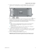
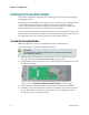
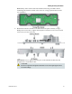
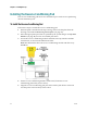
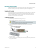
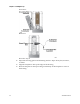
Table Of Contents
- Important Safety Instructions
- Introducing the Addressable Multimedia Stretch Tap
- Introduction to This Document
- Who Should Use This Document
- Qualified Personnel
- Scope
- Document Version
- Installing the Tap
- Overview
- Tools and Torque Specifications
- Preparing for Installation
- Removing the Faceplate
- Installing the Stretch Tap on a Strand
- Installing the Stretch Tap in a Pedestal
- Installing Optional Modules
- Installing the Tiering Filter Module
- Installing the Reverse Conditioning Pad
- Mounting the Faceplate
- Connecting Coax Drop Cables
- Replacing the Local Oscillator Module
- Replacing the Power Supply
- Customer Support Information
- If You Have Questions
- Appendix A Technical Information
- Glossary
- A
- ac, AC
- AC/RF byass switch
- addressable
- aerial mount
- amplifier
- AMST
- attenuation
- attenuator
- ATX
- bit
- broadband
- CATV
- dB
- DC
- dc, DC
- DC/EQ
- decibel
- directional coupler (DC) module
- drop amplifier
- drop cable
- equalization
- equalizer
- F-connector
- FCC
- forward path
- frequency
- FSK
- ft-lb
- GHz
- GND
- headend
- HFC
- Hz
- in-lb
- ingress
- LCSI
- LED
- LO
- MHz
- MST
- MTS
- N-m
- passive
- PCB
- pedestal mount
- PTC
- PWB
- reverse path
- RF
- RMA
- SCTE
- splitter
- strand mount
- tap
- tilt
- torque
- trap
- UL
- V
- V AC
- V DC
- W
- Index
Mounting the Faceplate
78-4002497-01 Rev F 33
Mounting the Faceplate
After mounting the housing, connecting the feeder cables, and plugging in optional
modules as needed, you are ready to install the faceplate in the tap housing.
Upgrading the Faceplate
You can easily upgrade an existing Multimedia Stretch Tap (MST) to an Addressable
Multimedia Stretch Tap (AMST) by removing the MST faceplate and replacing it
with a new AMST faceplate. For further details, refer to the instructions below for
faceplate removal with feeder cables attached.
To Mount the Faceplate
1 If the housing is installed on a strand, go to step 2.
If the housing is installed in a pedestal, go to step 3.
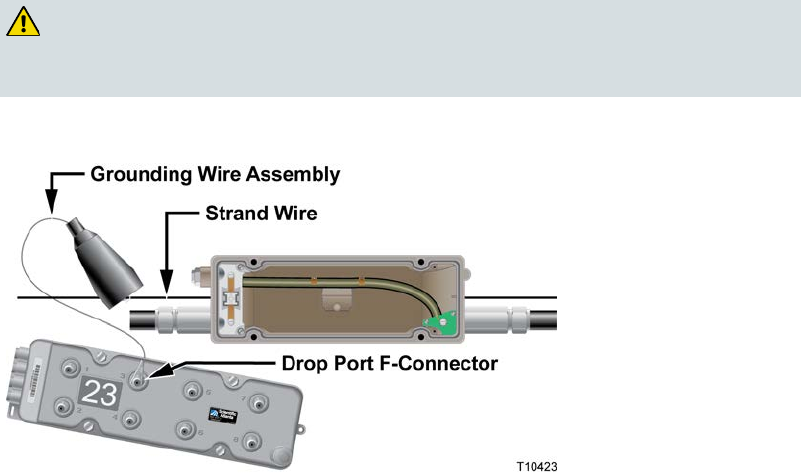
WARNING:
Protect yourself from electric shock and your equipment from damage.
Certain components can deliver an electrical shock.
2 Attach a grounding wire assembly to the strand wire and a drop port F-
connector.
Proceed to step 4.
3 Attach a grounding wire assembly to the strand clamp bolt on the pedestal and a
drop port F-connector.