
Installation Guide
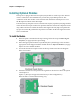
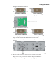
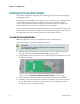
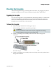
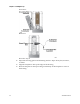
Table Of Contents
- Important Safety Instructions
- Introducing the Addressable Multimedia Stretch Tap
- Introduction to This Document
- Who Should Use This Document
- Qualified Personnel
- Scope
- Document Version
- Installing the Tap
- Overview
- Tools and Torque Specifications
- Preparing for Installation
- Removing the Faceplate
- Installing the Stretch Tap on a Strand
- Installing the Stretch Tap in a Pedestal
- Installing Optional Modules
- Installing the Tiering Filter Module
- Installing the Reverse Conditioning Pad
- Mounting the Faceplate
- Connecting Coax Drop Cables
- Replacing the Local Oscillator Module
- Replacing the Power Supply
- Customer Support Information
- If You Have Questions
- Appendix A Technical Information
- Glossary
- A
- ac, AC
- AC/RF byass switch
- addressable
- aerial mount
- amplifier
- AMST
- attenuation
- attenuator
- ATX
- bit
- broadband
- CATV
- dB
- DC
- dc, DC
- DC/EQ
- decibel
- directional coupler (DC) module
- drop amplifier
- drop cable
- equalization
- equalizer
- F-connector
- FCC
- forward path
- frequency
- FSK
- ft-lb
- GHz
- GND
- headend
- HFC
- Hz
- in-lb
- ingress
- LCSI
- LED
- LO
- MHz
- MST
- MTS
- N-m
- passive
- PCB
- pedestal mount
- PTC
- PWB
- reverse path
- RF
- RMA
- SCTE
- splitter
- strand mount
- tap
- tilt
- torque
- trap
- UL
- V
- V AC
- V DC
- W
- Index
Chapter 2 Installing the Tap
32 Rev E
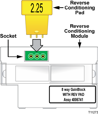
Installing the Reverse Conditioning Pad
The reverse conditioning pad allows for selectable tap loss in the reverse path using
discrete attenuator pads.
To Install the Reverse Conditioning Pad
Follow these steps to install the reverse conditioning pad.
1 If the faceplate is mounted in the tap housing, remove the faceplate from the
housing as described in Removing the Faceplate (on page 19).
2 Select the appropriate pad value as specified by the system design. See Tap Part
Numbers (on page 44) for a list of available pad values.
3 Locate the reverse conditioning module installed on the tap interface module
circuit board, as shown in the illustration below.
Note: This illustration shows the reverse conditioning module with the 8-way
GainBlock.
4 On the reverse conditioning module circuit board, locate the reverse
conditioning pad socket (shown above).
5 Align the reverse conditioning pad pins and insert the pad into the socket. Be
sure the pad is seated securely in the socket.