
Installation Guide
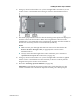
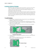
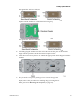
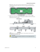
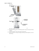
Table Of Contents
- Important Safety Instructions
- Introducing the Addressable Multimedia Stretch Tap
- Introduction to This Document
- Who Should Use This Document
- Qualified Personnel
- Scope
- Document Version
- Installing the Tap
- Overview
- Tools and Torque Specifications
- Preparing for Installation
- Removing the Faceplate
- Installing the Stretch Tap on a Strand
- Installing the Stretch Tap in a Pedestal
- Installing Optional Modules
- Installing the Tiering Filter Module
- Installing the Reverse Conditioning Pad
- Mounting the Faceplate
- Connecting Coax Drop Cables
- Replacing the Local Oscillator Module
- Replacing the Power Supply
- Customer Support Information
- If You Have Questions
- Appendix A Technical Information
- Glossary
- A
- ac, AC
- AC/RF byass switch
- addressable
- aerial mount
- amplifier
- AMST
- attenuation
- attenuator
- ATX
- bit
- broadband
- CATV
- dB
- DC
- dc, DC
- DC/EQ
- decibel
- directional coupler (DC) module
- drop amplifier
- drop cable
- equalization
- equalizer
- F-connector
- FCC
- forward path
- frequency
- FSK
- ft-lb
- GHz
- GND
- headend
- HFC
- Hz
- in-lb
- ingress
- LCSI
- LED
- LO
- MHz
- MST
- MTS
- N-m
- passive
- PCB
- pedestal mount
- PTC
- PWB
- reverse path
- RF
- RMA
- SCTE
- splitter
- strand mount
- tap
- tilt
- torque
- trap
- UL
- V
- V AC
- V DC
- W
- Index
Chapter 2 Installing the Tap
30 78-4002497-01 Rev F
Installing the Tiering Filter Module
This section describes the procedure for equipping the tap with an optional plug-in
tiering filter module.
Each tap port on the AMST can be remotely set to one of three states: RF On, RF Off,
or Tiered RF On. These remotely controlled states allow broadband network
operators to significantly reduce recurring operational expenses associated with
customer disconnects, reconnects, and basic service tier changes.
With an optional tiering filter installed and the tap set to the Tiered RF On state, only
RF within the passband of the tiering filter is connected to the tap port. This restricts
the signal delivered to the customer premise to a specific tier of service.
To Install the Tiering Filter Module
Note: Tiering filters can only be installed in Dual Tier addressable taps.
Follow these steps to install the tiering filter module.
CAUTION:
Avoid electrostatic discharge (ESD). Do not touch electronic components
when installing a module.
1 If the faceplate is mounted in the tap housing, remove the faceplate from the
housing as described in Removing the Faceplate (on page 19).
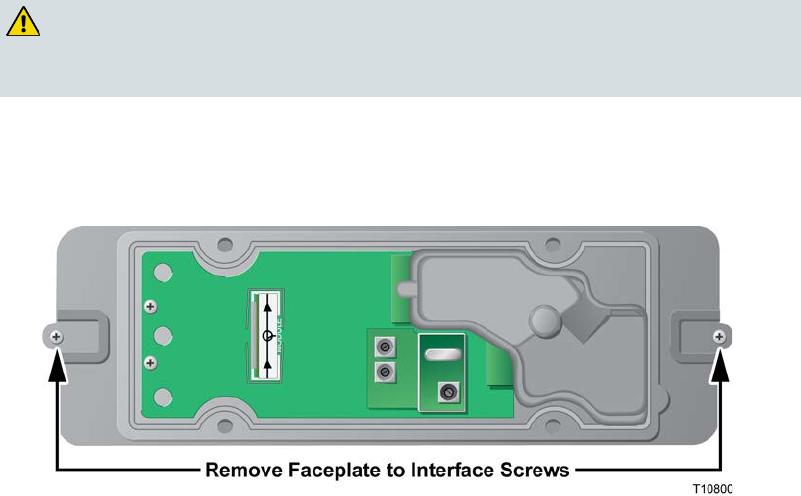
2 Using a Phillips-head screwdriver, remove the faceplate-to-interface screws from
the interface module.
3 Gently detach the interface module from the RF module faceplate assembly.
4 Carefully remove the tiering filter module and install the new module provided.
Be sure that all pins on the module align with the corresponding holes in the
tiering filter socket (see diagram below).