
Installation Guide
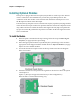
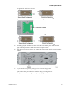
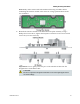
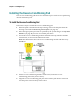
Table Of Contents
- Important Safety Instructions
- Introducing the Addressable Multimedia Stretch Tap
- Introduction to This Document
- Who Should Use This Document
- Qualified Personnel
- Scope
- Document Version
- Installing the Tap
- Overview
- Tools and Torque Specifications
- Preparing for Installation
- Removing the Faceplate
- Installing the Stretch Tap on a Strand
- Installing the Stretch Tap in a Pedestal
- Installing Optional Modules
- Installing the Tiering Filter Module
- Installing the Reverse Conditioning Pad
- Mounting the Faceplate
- Connecting Coax Drop Cables
- Replacing the Local Oscillator Module
- Replacing the Power Supply
- Customer Support Information
- If You Have Questions
- Appendix A Technical Information
- Glossary
- A
- ac, AC
- AC/RF byass switch
- addressable
- aerial mount
- amplifier
- AMST
- attenuation
- attenuator
- ATX
- bit
- broadband
- CATV
- dB
- DC
- dc, DC
- DC/EQ
- decibel
- directional coupler (DC) module
- drop amplifier
- drop cable
- equalization
- equalizer
- F-connector
- FCC
- forward path
- frequency
- FSK
- ft-lb
- GHz
- GND
- headend
- HFC
- Hz
- in-lb
- ingress
- LCSI
- LED
- LO
- MHz
- MST
- MTS
- N-m
- passive
- PCB
- pedestal mount
- PTC
- PWB
- reverse path
- RF
- RMA
- SCTE
- splitter
- strand mount
- tap
- tilt
- torque
- trap
- UL
- V
- V AC
- V DC
- W
- Index
Chapter 2 Installing the Tap
28 78-4002497-01 Rev F
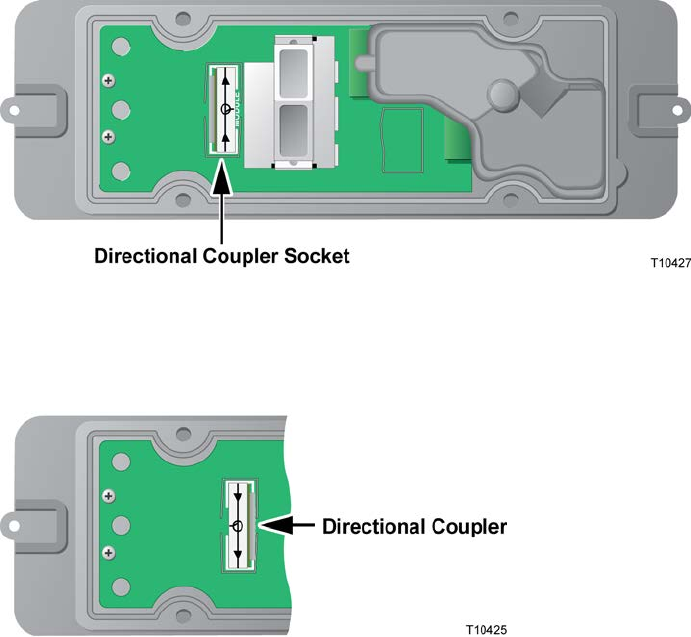
Installing Optional Modules
The tap uses a plug-in directional coupler (DC) module to set the tap value. The DC
value is selected for each installation to provide the proper RF input level. The
orientation of the DC module on the circuit board determines which port serves as
the RF input and which is the RF output.
If needed, the tap faceplate can use a directional coupler/equalizer (DC/EQ) module
in the directional coupler socket. The equalizer function controls the output tilt to the
drop cables and does not affect the feeder cable signal. The DC/EQ can equalize the
tap port across the RF passband in steps between 3 dB to 18 dB. The signal down the
line is not affected.
To Install the Module
1 If the faceplate is mounted in the tap housing, follow the steps in Removing the
Faceplate (on page 19) before proceeding.
2 Select the appropriate module as specified by the system design. Also select the
appropriate decal shipped with the module. Refer to Tap Part Numbers (on page
44) for a list of available modules.
3 Locate the directional coupler socket on the tap circuit board. See the diagram
below for location.
4 Orient the module to correspond to the signal flow direction as shown in Option
1 and Option 2.
Option 1: (The tap is shipped from the factory in this configuration.)
If the module is oriented the following way,