
Installation Guide
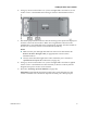
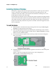
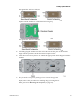
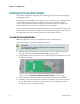
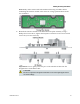
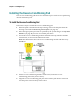
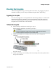
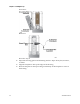
Table Of Contents
- Important Safety Instructions
- Introducing the Addressable Multimedia Stretch Tap
- Introduction to This Document
- Who Should Use This Document
- Qualified Personnel
- Scope
- Document Version
- Installing the Tap
- Overview
- Tools and Torque Specifications
- Preparing for Installation
- Removing the Faceplate
- Installing the Stretch Tap on a Strand
- Installing the Stretch Tap in a Pedestal
- Installing Optional Modules
- Installing the Tiering Filter Module
- Installing the Reverse Conditioning Pad
- Mounting the Faceplate
- Connecting Coax Drop Cables
- Replacing the Local Oscillator Module
- Replacing the Power Supply
- Customer Support Information
- If You Have Questions
- Appendix A Technical Information
- Glossary
- A
- ac, AC
- AC/RF byass switch
- addressable
- aerial mount
- amplifier
- AMST
- attenuation
- attenuator
- ATX
- bit
- broadband
- CATV
- dB
- DC
- dc, DC
- DC/EQ
- decibel
- directional coupler (DC) module
- drop amplifier
- drop cable
- equalization
- equalizer
- F-connector
- FCC
- forward path
- frequency
- FSK
- ft-lb
- GHz
- GND
- headend
- HFC
- Hz
- in-lb
- ingress
- LCSI
- LED
- LO
- MHz
- MST
- MTS
- N-m
- passive
- PCB
- pedestal mount
- PTC
- PWB
- reverse path
- RF
- RMA
- SCTE
- splitter
- strand mount
- tap
- tilt
- torque
- trap
- UL
- V
- V AC
- V DC
- W
- Index
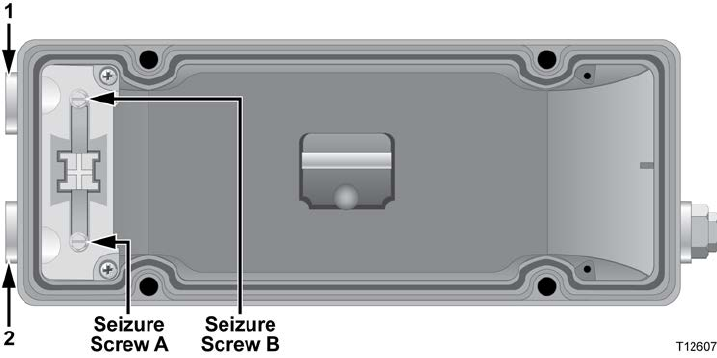
Installing the Stretch Tap in a Pedestal
78-4002497-01 Rev F 27
6 Using a 3/16-in. hex head driver or 3/16-in. straight blade screwdriver, loosen
seizure screws A and B inside the housing as shown in the illustration below.
7 Thread the prepared KS-connectors into the housing at the input and output port
locations 1 and 2 as shown above. Make sure to tighten the connector to the
manufacturer’s recommended torque specification (typically 15 ft-lb to 25 ft-lb or
20.3 N-m to 33.9 N-m), but not to exceed 60 ft-lb (81.3 N-m).
Notes:
Make sure the pass-through cable has been removed as described in To
Remove the Pass-Through Cable (on page 24) and as shown in the
illustration above.
Always ensure that the length of the center conductor pin is accurate as
explained in To Prepare the Connectors (on page 17).
8 Using a 3/16-in. hex head driver or 3/16-in. straight blade screwdriver, tighten
seizure screws A and B from 15 in-lb to 20 in-lb (1.7 N-m to 2.3 N-m). See the
diagram in step 6 for seizure screw locations.
9 Proceed to Installing Optional Modules (on page 28).
Important: Verify that the directional coupler (DC) on the faceplate is in the
correct orientation. The orientation depends on which port is the input port.