
Installation Guide
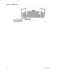
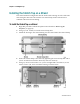
Table Of Contents
- Important Safety Instructions
- Introducing the Addressable Multimedia Stretch Tap
- Introduction to This Document
- Who Should Use This Document
- Qualified Personnel
- Scope
- Document Version
- Installing the Tap
- Overview
- Tools and Torque Specifications
- Preparing for Installation
- Removing the Faceplate
- Installing the Stretch Tap on a Strand
- Installing the Stretch Tap in a Pedestal
- Installing Optional Modules
- Installing the Tiering Filter Module
- Installing the Reverse Conditioning Pad
- Mounting the Faceplate
- Connecting Coax Drop Cables
- Replacing the Local Oscillator Module
- Replacing the Power Supply
- Customer Support Information
- If You Have Questions
- Appendix A Technical Information
- Glossary
- A
- ac, AC
- AC/RF byass switch
- addressable
- aerial mount
- amplifier
- AMST
- attenuation
- attenuator
- ATX
- bit
- broadband
- CATV
- dB
- DC
- dc, DC
- DC/EQ
- decibel
- directional coupler (DC) module
- drop amplifier
- drop cable
- equalization
- equalizer
- F-connector
- FCC
- forward path
- frequency
- FSK
- ft-lb
- GHz
- GND
- headend
- HFC
- Hz
- in-lb
- ingress
- LCSI
- LED
- LO
- MHz
- MST
- MTS
- N-m
- passive
- PCB
- pedestal mount
- PTC
- PWB
- reverse path
- RF
- RMA
- SCTE
- splitter
- strand mount
- tap
- tilt
- torque
- trap
- UL
- V
- V AC
- V DC
- W
- Index
Installing the Stretch Tap in a Pedestal
78-4002497-01 Rev F 25
Tools Needed
#2 blunt-nose Phillips-head screwdriver
3/8-in. or 1/2-in. wrench or nut driver
3/16-in. hex head driver or 3/16-in. straight-blade screwdriver
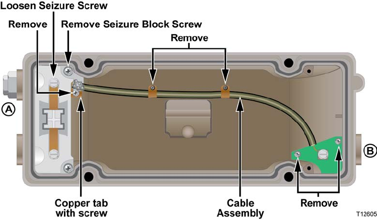
1 Using a 3/16-in. hex head driver or 3/16-in. straight-blade screwdriver, loosen
the seizure screw securing the pass-through cable at port A as shown in the
diagram below.
2 Using a #2 blunt-nose Phillips-head screwdriver, remove the six screws securing
the pass-through cable and printed wiring board (PWB) to the tap housing as
shown in the diagram above. Note that one screw is longer than the others
because it also secures the seizure block to the tap housing.
3 Pull the pass-through cable out of the seizure block, and then lift the entire cable
assembly with PWB attached out of the housing.
4 Using a 1/2-in. or 3/8-in. wrench, move the port end plug from location A to
location B as shown in the diagram above. Tighten the port end plug from 50 in-
lb to 60 in-lb (5.6 N-m to 6.8 N-m).