
Installation Guide
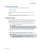
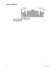
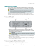
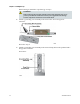
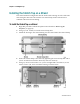
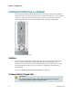
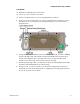
Table Of Contents
- Important Safety Instructions
- Introducing the Addressable Multimedia Stretch Tap
- Introduction to This Document
- Who Should Use This Document
- Qualified Personnel
- Scope
- Document Version
- Installing the Tap
- Overview
- Tools and Torque Specifications
- Preparing for Installation
- Removing the Faceplate
- Installing the Stretch Tap on a Strand
- Installing the Stretch Tap in a Pedestal
- Installing Optional Modules
- Installing the Tiering Filter Module
- Installing the Reverse Conditioning Pad
- Mounting the Faceplate
- Connecting Coax Drop Cables
- Replacing the Local Oscillator Module
- Replacing the Power Supply
- Customer Support Information
- If You Have Questions
- Appendix A Technical Information
- Glossary
- A
- ac, AC
- AC/RF byass switch
- addressable
- aerial mount
- amplifier
- AMST
- attenuation
- attenuator
- ATX
- bit
- broadband
- CATV
- dB
- DC
- dc, DC
- DC/EQ
- decibel
- directional coupler (DC) module
- drop amplifier
- drop cable
- equalization
- equalizer
- F-connector
- FCC
- forward path
- frequency
- FSK
- ft-lb
- GHz
- GND
- headend
- HFC
- Hz
- in-lb
- ingress
- LCSI
- LED
- LO
- MHz
- MST
- MTS
- N-m
- passive
- PCB
- pedestal mount
- PTC
- PWB
- reverse path
- RF
- RMA
- SCTE
- splitter
- strand mount
- tap
- tilt
- torque
- trap
- UL
- V
- V AC
- V DC
- W
- Index
Chapter 2 Installing the Tap
24 78-4002497-01 Rev F
Installing the Stretch Tap in a Pedestal
The pedestal-mounted configuration has the feeder cable entering and exiting the
unit on the same side. The tap without traps or filters fits in an 8-in. round or square
pedestal. A larger pedestal is needed if traps or filters are installed. Refer to the
following diagram for the recommended pedestal mounting configuration.
Guidelines
The housing is configured for typical strand mount where the feeder cable enters
one side of the housing and exits the other side. When installing the tap in a
pedestal, the feeder cable enters and exits the housing on the same side. To avoid
signal degradation in this case, it is necessary to completely remove the pass-
through cable.
Proceed to To Remove the Pass-Through Cable (on page 24).
To Remove the Pass-Through Cable
WARNING:
Do not perform this procedure when cables are entering any of the ports.
Certain components can deliver an electrical shock.