
Installation Guide
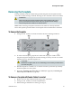
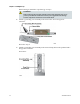
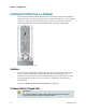
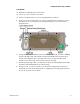
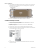
Table Of Contents
- Important Safety Instructions
- Introducing the Addressable Multimedia Stretch Tap
- Introduction to This Document
- Who Should Use This Document
- Qualified Personnel
- Scope
- Document Version
- Installing the Tap
- Overview
- Tools and Torque Specifications
- Preparing for Installation
- Removing the Faceplate
- Installing the Stretch Tap on a Strand
- Installing the Stretch Tap in a Pedestal
- Installing Optional Modules
- Installing the Tiering Filter Module
- Installing the Reverse Conditioning Pad
- Mounting the Faceplate
- Connecting Coax Drop Cables
- Replacing the Local Oscillator Module
- Replacing the Power Supply
- Customer Support Information
- If You Have Questions
- Appendix A Technical Information
- Glossary
- A
- ac, AC
- AC/RF byass switch
- addressable
- aerial mount
- amplifier
- AMST
- attenuation
- attenuator
- ATX
- bit
- broadband
- CATV
- dB
- DC
- dc, DC
- DC/EQ
- decibel
- directional coupler (DC) module
- drop amplifier
- drop cable
- equalization
- equalizer
- F-connector
- FCC
- forward path
- frequency
- FSK
- ft-lb
- GHz
- GND
- headend
- HFC
- Hz
- in-lb
- ingress
- LCSI
- LED
- LO
- MHz
- MST
- MTS
- N-m
- passive
- PCB
- pedestal mount
- PTC
- PWB
- reverse path
- RF
- RMA
- SCTE
- splitter
- strand mount
- tap
- tilt
- torque
- trap
- UL
- V
- V AC
- V DC
- W
- Index
Chapter 2 Installing the Tap
22 78-4002497-01 Rev F
Installing the Stretch Tap on a Strand
The strand-mounted configuration has the feeder cable entering one side of the unit
and exiting the other side. The unit has one strand clamp with a bolt and uses a
standard cable strand for mounting.
To Install the Stretch Tap on a Strand
1 Begin this procedure with the faceplate removed. Refer to Removing the
Faceplate (on page 19).
2 Using a 3/8-in. wrench, loosen the strand clamp bolt.
3 Attach the housing to the strand making sure the strand enters the strand clamp.
4 Secure the strand clamp to the strand by tightening the strand clamp bolt with a
3/8-in. wrench from 30 in-lb to 40 in-lb (3.4 N-m to 4.5 N-m).
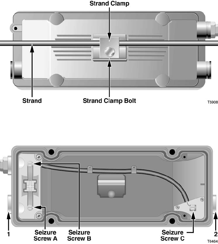
5 Using a 3/16-in. hex head driver or 3/16-in. straight blade screwdriver, loosen
seizure screws A, B, and C inside the housing as shown below.