
Installation Guide
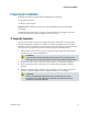
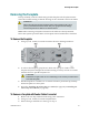
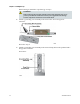
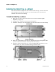
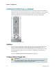
Table Of Contents
- Important Safety Instructions
- Introducing the Addressable Multimedia Stretch Tap
- Introduction to This Document
- Who Should Use This Document
- Qualified Personnel
- Scope
- Document Version
- Installing the Tap
- Overview
- Tools and Torque Specifications
- Preparing for Installation
- Removing the Faceplate
- Installing the Stretch Tap on a Strand
- Installing the Stretch Tap in a Pedestal
- Installing Optional Modules
- Installing the Tiering Filter Module
- Installing the Reverse Conditioning Pad
- Mounting the Faceplate
- Connecting Coax Drop Cables
- Replacing the Local Oscillator Module
- Replacing the Power Supply
- Customer Support Information
- If You Have Questions
- Appendix A Technical Information
- Glossary
- A
- ac, AC
- AC/RF byass switch
- addressable
- aerial mount
- amplifier
- AMST
- attenuation
- attenuator
- ATX
- bit
- broadband
- CATV
- dB
- DC
- dc, DC
- DC/EQ
- decibel
- directional coupler (DC) module
- drop amplifier
- drop cable
- equalization
- equalizer
- F-connector
- FCC
- forward path
- frequency
- FSK
- ft-lb
- GHz
- GND
- headend
- HFC
- Hz
- in-lb
- ingress
- LCSI
- LED
- LO
- MHz
- MST
- MTS
- N-m
- passive
- PCB
- pedestal mount
- PTC
- PWB
- reverse path
- RF
- RMA
- SCTE
- splitter
- strand mount
- tap
- tilt
- torque
- trap
- UL
- V
- V AC
- V DC
- W
- Index
Removing the Faceplate
78-4002497-01 Rev F 19
Removing the Faceplate
The tap assembly consists of the housing and the faceplate. The faceplate must be
removed from the housing so that the housing can be connected to the feeder cables.
WARNING:
When removing the faceplate with the feeder cables attached, take care to
protect yourself from electrical shock and your equipment from damage.
Certain components can deliver an electrical shock.
Note: When removing a faceplate when the feeder cables are already attached,
follow the separate procedure below for faceplate removal with feeders connected.
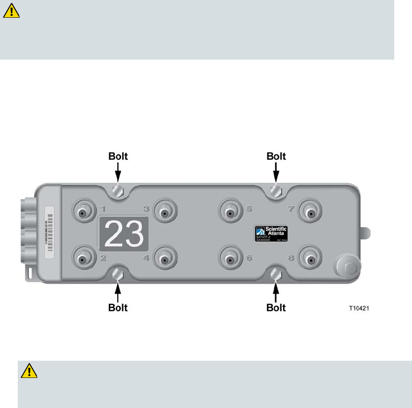
To Remove the Faceplate
1 Using a 3/8-in. wrench, loosen the four bolts shown in the diagram below.
2 To remove the faceplate, grasp the two bolts near drop ports 1 and 2 on the
faceplate and pull it straight out from the housing. You may need to use a small
amount of force to pull the faceplate out.
CAUTION:
Handle the faceplate with care to avoid damage to the circuitry mounted to the
rear of the faceplate.
3 Put the faceplate in a small box or on a block of foam to protect the tap circuitry.
Set the faceplate in a secure place.
4 Proceed to Installing the Stretch Tap on a Strand (on page 22) or Installing the
Stretch Tap in a Pedestal (on page 24).
To Remove a Faceplate with Feeder Cables Connected
1 Remove all coax drop cables from the drop port F-connectors.
2 Using a 3/8-in. wrench, loosen the faceplate bolts.
3 If the housing is installed on a strand, go to step 4.