
Installation Guide
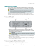
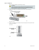
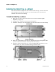
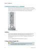
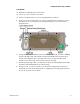
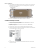
Table Of Contents
- Important Safety Instructions
- Introducing the Addressable Multimedia Stretch Tap
- Introduction to This Document
- Who Should Use This Document
- Qualified Personnel
- Scope
- Document Version
- Installing the Tap
- Overview
- Tools and Torque Specifications
- Preparing for Installation
- Removing the Faceplate
- Installing the Stretch Tap on a Strand
- Installing the Stretch Tap in a Pedestal
- Installing Optional Modules
- Installing the Tiering Filter Module
- Installing the Reverse Conditioning Pad
- Mounting the Faceplate
- Connecting Coax Drop Cables
- Replacing the Local Oscillator Module
- Replacing the Power Supply
- Customer Support Information
- If You Have Questions
- Appendix A Technical Information
- Glossary
- A
- ac, AC
- AC/RF byass switch
- addressable
- aerial mount
- amplifier
- AMST
- attenuation
- attenuator
- ATX
- bit
- broadband
- CATV
- dB
- DC
- dc, DC
- DC/EQ
- decibel
- directional coupler (DC) module
- drop amplifier
- drop cable
- equalization
- equalizer
- F-connector
- FCC
- forward path
- frequency
- FSK
- ft-lb
- GHz
- GND
- headend
- HFC
- Hz
- in-lb
- ingress
- LCSI
- LED
- LO
- MHz
- MST
- MTS
- N-m
- passive
- PCB
- pedestal mount
- PTC
- PWB
- reverse path
- RF
- RMA
- SCTE
- splitter
- strand mount
- tap
- tilt
- torque
- trap
- UL
- V
- V AC
- V DC
- W
- Index

Preparing for Installation
78-4002497-01 Rev F 17
Preparing for Installation
Complete the following tasks before installing the tap housing.
Prepare connectors
Remove the faceplate
Important: The installer should review and install this product per EN 50083-
1/A2:1998.
Confirm that the shunt power directors for the amplifier preceding the tap in the
cascade are installed so that the AMST can receive power.
To Prepare the Connectors
The tap requires KS-connectors for input and output connections. The connectors,
with pins extending 1.5 inches to 1.6 inches (38 mm to 41 mm) from the connector
shoulder, require no trimming. You must trim longer pins before inserting them into
the housing. To prepare the connector, follow the steps in the table below.
1 Cut the feeder cable to allow proper entry into the port while also allowing for
expansion loops in strand installations.
WARNING:
Avoid electrical shock and damage to this product. If AC is present on the
cable, take care to avoid electrocution or short circuits when cutting the cable.
2 Prepare the cable ends per the cable manufacturer’s recommended method.
3 Place the connector above the entry port so that it lines up with its installed
position.
4 If the pin extends past the stripline on the housing, use wire cutters to trim the
pin flush with the stripline. See the diagram below for a visual guide.
CAUTION:
Always ensure that the length of the center conductor pin is accurate.
Excessive length could damage the connection beam housing and cause
performance problems in the unit.