
Installation Guide

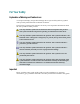
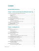
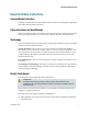
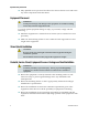
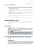
Table Of Contents
- Important Safety Instructions
- Introducing the Addressable Multimedia Stretch Tap
- Introduction to This Document
- Who Should Use This Document
- Qualified Personnel
- Scope
- Document Version
- Installing the Tap
- Overview
- Tools and Torque Specifications
- Preparing for Installation
- Removing the Faceplate
- Installing the Stretch Tap on a Strand
- Installing the Stretch Tap in a Pedestal
- Installing Optional Modules
- Installing the Tiering Filter Module
- Installing the Reverse Conditioning Pad
- Mounting the Faceplate
- Connecting Coax Drop Cables
- Replacing the Local Oscillator Module
- Replacing the Power Supply
- Customer Support Information
- If You Have Questions
- Appendix A Technical Information
- Glossary
- A
- ac, AC
- AC/RF byass switch
- addressable
- aerial mount
- amplifier
- AMST
- attenuation
- attenuator
- ATX
- bit
- broadband
- CATV
- dB
- DC
- dc, DC
- DC/EQ
- decibel
- directional coupler (DC) module
- drop amplifier
- drop cable
- equalization
- equalizer
- F-connector
- FCC
- forward path
- frequency
- FSK
- ft-lb
- GHz
- GND
- headend
- HFC
- Hz
- in-lb
- ingress
- LCSI
- LED
- LO
- MHz
- MST
- MTS
- N-m
- passive
- PCB
- pedestal mount
- PTC
- PWB
- reverse path
- RF
- RMA
- SCTE
- splitter
- strand mount
- tap
- tilt
- torque
- trap
- UL
- V
- V AC
- V DC
- W
- Index

For Your Safety
Explanation of Warning and Caution Icons
Avoid personal injury and product damage! Do not proceed beyond any symbol
until you fully understand the indicated conditions.
The following warning and caution icons alert you to important information about
the safe operation of this product:
You may find this symbol in the document that accompanies this product.
This symbol indicates important operating or maintenance instructions.
You may find this symbol affixed to the product. This symbol indicates a live
terminal where a dangerous voltage may be present; the tip of the flash points
to the terminal device.
You may find this symbol affixed to the product. This symbol indicates a
protective ground terminal.
You may find this symbol affixed to the product. This symbol indicates a
chassis terminal (normally used for equipotential bonding).
You may find this symbol affixed to the product. This symbol warns of a
potentially hot surface.
You may find this symbol affixed to the product and in this document. This
symbol indicates an infrared laser that transmits intensity-modulated light
and emits invisible laser radiation or an LED that transmits intensity-
modulated light.
Important
Please read this entire guide. If this guide provides installation or operation
instructions, give particular attention to all safety statements included in this guide.