
Installation Guide
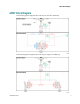

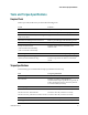

Table Of Contents
- Important Safety Instructions
- Introducing the Addressable Multimedia Stretch Tap
- Introduction to This Document
- Who Should Use This Document
- Qualified Personnel
- Scope
- Document Version
- Installing the Tap
- Overview
- Tools and Torque Specifications
- Preparing for Installation
- Removing the Faceplate
- Installing the Stretch Tap on a Strand
- Installing the Stretch Tap in a Pedestal
- Installing Optional Modules
- Installing the Tiering Filter Module
- Installing the Reverse Conditioning Pad
- Mounting the Faceplate
- Connecting Coax Drop Cables
- Replacing the Local Oscillator Module
- Replacing the Power Supply
- Customer Support Information
- If You Have Questions
- Appendix A Technical Information
- Glossary
- A
- ac, AC
- AC/RF byass switch
- addressable
- aerial mount
- amplifier
- AMST
- attenuation
- attenuator
- ATX
- bit
- broadband
- CATV
- dB
- DC
- dc, DC
- DC/EQ
- decibel
- directional coupler (DC) module
- drop amplifier
- drop cable
- equalization
- equalizer
- F-connector
- FCC
- forward path
- frequency
- FSK
- ft-lb
- GHz
- GND
- headend
- HFC
- Hz
- in-lb
- ingress
- LCSI
- LED
- LO
- MHz
- MST
- MTS
- N-m
- passive
- PCB
- pedestal mount
- PTC
- PWB
- reverse path
- RF
- RMA
- SCTE
- splitter
- strand mount
- tap
- tilt
- torque
- trap
- UL
- V
- V AC
- V DC
- W
- Index

Tools and Torque Specifications
78-4002497-01 Rev F 15
Tools and Torque Specifications
Required Tools
Before you start, make sure you have the following tools.
Tools Used to. . .
3/8-in. hex wrench, or nut driver Tighten strand clamp bolts and retainer bolts
1/2-in. or 3/8-in. wrench, or nut driver Remove and replace cable end plugs
3/16-in. hex nut driver or 3/16-in straight-
blade screwdriver
Tighten seizure screws
#2 blunt-nose Phillips-head screwdriver Remove pass-through cable mounting screws
Wire cutters or snips Cut cable, trim center conductor length
Torque wrench in in-lb
(0 in-lb to 250 in-lb minimum)
(0 N-m to 28.2 N-m minimum)
Tighten seizure screws, connectors, and
retainer bolts
Insulated pliers Install or remove PTCs for power passing
Grounding wire assembly, part number
569533 (for hot installation only)
Prevent electric shock and equipment damage.
Certain components can deliver an electrical
shock.
Torque Specifications
The following are recommended torque specifications for the tap.
Part Torque Specification
Strand clamp bolt 30 in-lb to 40 in-lb (3.4 N-m to 4.5 N-m)
KS-connector Tighten according to manufacturer’s
recommended torque specification, typically 15
ft-lb to 25 ft-lb (20.3 N-m to 33.9 N-m), but not
to exceed 60 ft-lb (81.3 N-m)
Port end plug 50 in-lb to 60 in-lb (5.6 N-m to 6.8 N-m)
Seizure screw A and C
Seizure screw B: strand mount
Seizure screw B: pedestal or lock box mount
15 in-lb to 20 in-lb (1.7 N-m to 2.3 N-m)
12 in-lb to 15 in-lb (1.4 N-m to 1.7 N-m)
15 in-lb to 20 in-lb (1.7 N-m to 2.3 N-m)
Seizure block screw 10 in-lb (1.13 N-m)
Housing closure bolt 50 in-lb to 60 in-lb (5.6 N-m to 6.8 N-m)