
Installation Guide

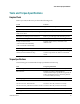

Table Of Contents
- Important Safety Instructions
- Introducing the Addressable Multimedia Stretch Tap
- Introduction to This Document
- Who Should Use This Document
- Qualified Personnel
- Scope
- Document Version
- Installing the Tap
- Overview
- Tools and Torque Specifications
- Preparing for Installation
- Removing the Faceplate
- Installing the Stretch Tap on a Strand
- Installing the Stretch Tap in a Pedestal
- Installing Optional Modules
- Installing the Tiering Filter Module
- Installing the Reverse Conditioning Pad
- Mounting the Faceplate
- Connecting Coax Drop Cables
- Replacing the Local Oscillator Module
- Replacing the Power Supply
- Customer Support Information
- If You Have Questions
- Appendix A Technical Information
- Glossary
- A
- ac, AC
- AC/RF byass switch
- addressable
- aerial mount
- amplifier
- AMST
- attenuation
- attenuator
- ATX
- bit
- broadband
- CATV
- dB
- DC
- dc, DC
- DC/EQ
- decibel
- directional coupler (DC) module
- drop amplifier
- drop cable
- equalization
- equalizer
- F-connector
- FCC
- forward path
- frequency
- FSK
- ft-lb
- GHz
- GND
- headend
- HFC
- Hz
- in-lb
- ingress
- LCSI
- LED
- LO
- MHz
- MST
- MTS
- N-m
- passive
- PCB
- pedestal mount
- PTC
- PWB
- reverse path
- RF
- RMA
- SCTE
- splitter
- strand mount
- tap
- tilt
- torque
- trap
- UL
- V
- V AC
- V DC
- W
- Index

Chapter 1 Introducing the Addressable Multimedia Stretch Tap
10 78-4002497-01 Rev F
AMST Component Descriptions
The table below describes the functions of the tap components.
Module Function
Digital
microcontroller and
memory
Receives data from the receiver, deciphers it, and carries out
instructions. The microcontroller in each tap has its own address
range, and any individual tap or port can be controlled from the
headend.
Firmware and data protocol is compatible with the AT Manager
software. It emulates a model 8550 home terminal.
Turns either tier of the RF path on each port on or off.
Performs local refresh at predetermined intervals.
Manages LCSI communications.
Interface PCB
Receives RF and AC from the input.
Plug-in directional coupler module sends some of the RF signal to
the tap ports, while the rest is passed to the output of the unit.
Additional 17 dB coupler sends RF to the receiver through coupled
leg. The remaining RF signal on the through coupled leg passes to
the splitter and switch modules.
Most AC current passes from input to output through the high
current AC bypass coil. A small amount of current is picked off
with a smaller RF choke and sent to the power supply and port-
powering module.
Receiver
Takes the data that has been FSK (frequency-shift key) modulated
onto an RF carrier and demodulates it back to down to 5 V digital
data.
The receiver has a front-end bandpass filter that rejects image
frequencies.
The amplifier in the receiver boosts the carrier signal to an
acceptable level and provides isolation from local oscillator (LO)
leakage.
The demodulated data is sent to the digital microcontroller.
Tiering filter
Provides partial channel availability service as dictated by the
chosen tiering filter value. Refer to Installing the Tiering Filter
Module (on page 30).
Local Oscillator (LO)
Establishes the FSK communications frequency in which the tap
operates.
Directional Coupler
(DC)
Determines the tap loss value of the unit.
The DC value is selected for each installation to provide the proper
RF input level.