
Installation Guide

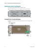
Table Of Contents
- Important Safety Instructions
- Introducing the Addressable Multimedia Stretch Tap
- Introduction to This Document
- Who Should Use This Document
- Qualified Personnel
- Scope
- Document Version
- Installing the Tap
- Overview
- Tools and Torque Specifications
- Preparing for Installation
- Removing the Faceplate
- Installing the Stretch Tap on a Strand
- Installing the Stretch Tap in a Pedestal
- Installing Optional Modules
- Installing the Tiering Filter Module
- Installing the Reverse Conditioning Pad
- Mounting the Faceplate
- Connecting Coax Drop Cables
- Replacing the Local Oscillator Module
- Replacing the Power Supply
- Customer Support Information
- If You Have Questions
- Appendix A Technical Information
- Glossary
- A
- ac, AC
- AC/RF byass switch
- addressable
- aerial mount
- amplifier
- AMST
- attenuation
- attenuator
- ATX
- bit
- broadband
- CATV
- dB
- DC
- dc, DC
- DC/EQ
- decibel
- directional coupler (DC) module
- drop amplifier
- drop cable
- equalization
- equalizer
- F-connector
- FCC
- forward path
- frequency
- FSK
- ft-lb
- GHz
- GND
- headend
- HFC
- Hz
- in-lb
- ingress
- LCSI
- LED
- LO
- MHz
- MST
- MTS
- N-m
- passive
- PCB
- pedestal mount
- PTC
- PWB
- reverse path
- RF
- RMA
- SCTE
- splitter
- strand mount
- tap
- tilt
- torque
- trap
- UL
- V
- V AC
- V DC
- W
- Index
Chapter 1 Introducing the Addressable Multimedia Stretch Tap
4 78-4002497-01 Rev F
A plug-in directional coupler allows for easy change of tap value, signal
direction, or reverse conditioning.
Reverse Conditioning Module allows for selectable tap loss in the reverse path
using discrete attenuator pads.
When purchased as a dual unit, each AMST port can be switched to either one of
the two tiers, or turned off individually.
The AMST is a low power consumption unit.
The tiering filter provides customers access to different levels of service.
Field-replaceable power supply, gainblock, LO, tiering filter, directional coupler,
and reverse conditioning module.
Local craft serial interface (LCSI) allows monitoring of the port status at the tap.
This option is available separately along with the interface cable required to
connect from a laptop to the AMST. Refer to the Addressable Multimedia Stretch
Tap Local Craft Serial Interface (LCSI) Installation Instructions, part number 4005053.
Housing Features
9-inch housing spans the typical gap left in the feeder cable after removing old
taps. This allows for tap upgrades without adding splices or extension
connectors to the feeder cable.
Patented Connection Beam AC/RF bypass allows for removal of the tap
faceplate without interrupting downstream customer service.
The AMST housing is the same as that used for the Multimedia Stretch Tap
(MST). This allows the customer to upgrade the existing MST faceplate to an
AMST faceplate without having to replace the tap housing.
Faceplate Components
The AMST faceplate assembly consists of the following components.
Interface printed circuit board (PCB), consisting of:
- Receiver module
- RF coupler
- Gainblock
- Local Oscillator (LO)
- Reverse Conditioning module
RF PCB, consisting of:
- Splitters and switches