
Installation Guide

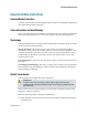
Table Of Contents
- Important Safety Instructions
- Introducing the Addressable Multimedia Stretch Tap
- Introduction to This Document
- Who Should Use This Document
- Qualified Personnel
- Scope
- Document Version
- Installing the Tap
- Overview
- Tools and Torque Specifications
- Preparing for Installation
- Removing the Faceplate
- Installing the Stretch Tap on a Strand
- Installing the Stretch Tap in a Pedestal
- Installing Optional Modules
- Installing the Tiering Filter Module
- Installing the Reverse Conditioning Pad
- Mounting the Faceplate
- Connecting Coax Drop Cables
- Replacing the Local Oscillator Module
- Replacing the Power Supply
- Customer Support Information
- If You Have Questions
- Appendix A Technical Information
- Glossary
- A
- ac, AC
- AC/RF byass switch
- addressable
- aerial mount
- amplifier
- AMST
- attenuation
- attenuator
- ATX
- bit
- broadband
- CATV
- dB
- DC
- dc, DC
- DC/EQ
- decibel
- directional coupler (DC) module
- drop amplifier
- drop cable
- equalization
- equalizer
- F-connector
- FCC
- forward path
- frequency
- FSK
- ft-lb
- GHz
- GND
- headend
- HFC
- Hz
- in-lb
- ingress
- LCSI
- LED
- LO
- MHz
- MST
- MTS
- N-m
- passive
- PCB
- pedestal mount
- PTC
- PWB
- reverse path
- RF
- RMA
- SCTE
- splitter
- strand mount
- tap
- tilt
- torque
- trap
- UL
- V
- V AC
- V DC
- W
- Index

Important Safety Instructions
viii 78-4002497-01 Rev F
To properly ground this equipment, follow these safety guidelines:
Grounding-Type Plug - For a 3-terminal plug (one terminal on this plug is a
protective grounding pin), insert the plug into a grounded mains, 3-terminal
outlet.
Note: This plug fits only one way. If this plug cannot be fully inserted into the
outlet, contact an electrician to replace the obsolete 3-terminal outlet.
Polarized Plug - For a 2-terminal plug (a polarized plug with one wide blade
and one narrow blade), insert the plug into a polarized mains, 2-terminal outlet
in which one socket is wider than the other.
Note: If this plug cannot be fully inserted into the outlet, try reversing the plug.
If the plug still fails to fit, contact an electrician to replace the obsolete 2-terminal
outlet.
Grounding Terminal
If this equipment is equipped with an external grounding terminal, attach one end of
an 18-gauge wire (or larger) to the grounding terminal; then, attach the other end of
the wire to a ground, such as a grounded equipment rack.
Safety Plugs (European Union)
Class I Mains Powered Equipment – Provided with a 3-terminal AC inlet and
requires connection to a 3-terminal mains supply outlet via a 3-terminal power
cord for proper connection to the protective ground.
Note: The equipotential bonding terminal provided on some equipment is not
designed to function as a protective ground connection.
Class II Mains Powered Equipment – Provided with a 2-terminal AC inlet that
may be connected by a 2-terminal power cord to the mains supply outlet. No
connection to the protective ground is required as this class of equipment is
provided with double or reinforced and/or supplementary insulation in
addition to the basic insulation provided in Class I equipment.
Note: Class II equipment, which is subject to EN 50083-1, is provided with a
chassis mounted equipotential bonding terminal. See the section titled
Equipotential Bonding for connection instructions.
Equipotential Bonding
If this equipment is equipped with an external chassis terminal marked with the IEC
60417-5020 chassis icon (
), the installer should refer to CENELEC standard EN
50083-1 or IEC standard IEC 60728-11 for correct equipotential bonding connection
instructions.