Rev E Addressable Multimedia Stretch Tap with Tiering Capability Installation and Operation Guide
For Your Safety Explanation of Warning and Caution Icons Avoid personal injury and product damage! Do not proceed beyond any symbol until you fully understand the indicated conditions. The following warning and caution icons alert you to important information about the safe operation of this product: You may find this symbol in the document that accompanies this product. This symbol indicates important operating or maintenance instructions. You may find this symbol affixed to the product.
Notices Trademark Acknowledgments Cisco and the Cisco logo are trademarks or registered trademarks of Cisco and/or its affiliates in the U.S. and other countries. To view a list of cisco trademarks, go to this URL: www.cisco.com/go/trademarks. ATX is a registered Trademark of ATX Telecom Systems, Inc. Other third party trademarks mentioned are the property of their respective owners. The use of the word partner does not imply a partnership relationship between Cisco and any other company.
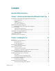
Contents Important Safety Instructions v Chapter 1 Introducing the Addressable Multimedia Stretch Tap 1 Description of the Addressable Multimedia Stretch Tap ................................................... 3 Tap Components ......................................................................................................... 3 Features ........................................................................................................................ 3 Housing Features ........................
Contents Installing the Reverse Conditioning Pad ............................................................................ 32 To Install the Reverse Conditioning Pad ............................................................... 32 Mounting the Faceplate ........................................................................................................ 33 Upgrading the Faceplate .......................................................................................... 33 To Mount the Faceplate ...
Important Safety Instructions Important Safety Instructions Read and Retain Instructions Carefully read all safety and operating instructions before operating this equipment, and retain them for future reference. Follow Instructions and Heed Warnings Follow all operating and use instructions. Pay attention to all warnings and cautions in the operating instructions, as well as those that are affixed to this equipment. Terminology The terms defined below are used in this document.
Important Safety Instructions Only qualified service personnel are allowed to remove chassis covers and access any of the components inside the chassis. Equipment Placement WARNING: Avoid personal injury and damage to this equipment. An unstable mounting surface may cause this equipment to fall. To protect against equipment damage or injury to personnel, comply with the following: Install this equipment in a restricted access location (access restricted to service personnel).
Important Safety Instructions Connecting to Utility AC Power Important: If this equipment is a Class I equipment, it must be grounded. If this equipment plugs into an outlet, the outlet must be near this equipment, and must be easily accessible. Connect this equipment only to the power sources that are identified on the equipment-rating label, which is normally located close to the power inlet connector(s). This equipment may have two power sources.
Important Safety Instructions To properly ground this equipment, follow these safety guidelines: Grounding-Type Plug - For a 3-terminal plug (one terminal on this plug is a protective grounding pin), insert the plug into a grounded mains, 3-terminal outlet. Note: This plug fits only one way. If this plug cannot be fully inserted into the outlet, contact an electrician to replace the obsolete 3-terminal outlet.
Important Safety Instructions General Servicing Precautions WARNING: Avoid electric shock! Opening or removing this equipment’s cover may expose you to dangerous voltages. CAUTION: These servicing precautions are for the guidance of qualified service personnel only. To reduce the risk of electric shock, do not perform any servicing other than that contained in the operating instructions unless you are qualified to do so. Refer all servicing to qualified service personnel.
Important Safety Instructions Avoid touching electronic components when installing a module. Fuse Replacement To replace a fuse, comply with the following: Disconnect the power before changing fuses. Identify and clear the condition that caused the original fuse failure. Always use a fuse of the correct type and rating. The correct type and rating are indicated on this equipment.
Important Safety Instructions Accessories Use only attachments or accessories specified by the manufacturer. Electromagnetic Compatibility Regulatory Requirements This equipment meets applicable electromagnetic compatibility (EMC) regulatory requirements. Refer to this equipment's data sheet for details about regulatory compliance approvals.
1 Chapter 1 Introducing the Addressable Multimedia Stretch Tap Introduction to This Document This guide introduces the Addressable Multimedia Strech™ Tap with Tiering Capability. The tap is designed to provide signal from the feeder cable to the drop. It is available in 4-, 8-, 12-, and 16-port configurations and in a wide range of tap values. Interchangeable directional couplers (DCs) make it easy to change tap values and apply signal conditioning to equalize the RF plant.
Scope This guide discusses the following topics. Installing the tap on a strand Installing the tap in a pedestal Installing optional modules in the tap Enabling drop powering Connecting coax drop cables Document Version This is the fifth release of this guide (Rev E). In This Chapter 2 Description of the Addressable Multimedia Stretch Tap .................. 3 Multimedia Stretch Tap Diagram ......................................................... 6 Optional Modules ................
Description of the Addressable Multimedia Stretch Tap Description of the Addressable Multimedia Stretch Tap The Addressable Multimedia Stretch Tap (AMST) with Tiering Capability is an enhanced version of the Multimedia Stretch Tap with an embedded computer. A cable operator can activate or deactivate AMST ports from the Addressable Tap (AT) Manager or billing system in the central office or headend, alleviating the need to dispatch a service crew. Each AMST contains a unique address range stored in memory.
Chapter 1 Introducing the Addressable Multimedia Stretch Tap A plug-in directional coupler allows for easy change of tap value, signal direction, or reverse conditioning. Reverse Conditioning Module allows for selectable tap loss in the reverse path using discrete attenuator pads. When purchased as a dual unit, each AMST port can be switched to either one of the two tiers, or turned off individually. The AMST is a low power consumption unit.
Description of the Addressable Multimedia Stretch Tap - Digital microcontroller and memory - Port powering module (12- and 16-port units only) - Local Craft Serial Interface (LCSI) connector - Tiering filter Power supply module Bar code labels containing the port digital addresses 78-4002497-01 Rev F 5
Chapter 1 Introducing the Addressable Multimedia Stretch Tap Multimedia Stretch Tap Diagram The following diagram shows an 8-way AMST faceplate. Note: The AMST faceplate may vary slightly depending on the model. Housing with Pass-Through Cable Diagram The following diagram shows the 9-inch housing with the pass-through cable installed.
Optional Modules Optional Modules The tap accepts several types of modules that define specific tap functions. Directional Coupler (DC) The plug-in directional coupler (DC) module sets the tap value. The orientation of the DC determines the RF flow through the tap. The DC is a plug-in module that is installed in the field. Refer to Installing Optional Modules (on page 28) for installation instructions. Refer to Tap Part Numbers (on page 44) for a listing of available tap values.
Chapter 1 Introducing the Addressable Multimedia Stretch Tap AMST Bar Code Digital Addresses Bar code labels on the side of the AMST contain the serial number and hexadecimal address of each port. The first nine characters give the port serial number and the last seven characters give the port address. The Port 1 seral number is also considered to be the serial number of the entire tap. An example of the bar code label character definition is as follows.
AMST Block Diagram AMST Block Diagram The following block diagram shows the 4-port, dual tier AMST tap. The following block diagram shows the 8-port, single tier AMST tap.
Chapter 1 Introducing the Addressable Multimedia Stretch Tap AMST Component Descriptions The table below describes the functions of the tap components. Module Function Digital microcontroller and memory Receives data from the receiver, deciphers it, and carries out instructions. The microcontroller in each tap has its own address range, and any individual tap or port can be controlled from the headend. Firmware and data protocol is compatible with the AT Manager software.
AMST Component Descriptions Module Function Reverse Conditioning module Allows for selectable tap loss in the reverse path using discrete attenuator pads. Gainblock Adds gain in both the forward and reverse paths. This is necessary to allow the AMST to "drop-in" to existing plant designs. Power supply Converts the AC voltage on the input to a well-regulated DC voltage for station powering.
2 Chapter 2 Installing the Tap This chapter gives step-by-step instructions for installing the tap in your cable system. In This Chapter 78-4002497-01 Rev F Overview ................................................................................................ 14 Tools and Torque Specifications ......................................................... 15 Preparing for Installation ..................................................................... 17 Removing the Faceplate .
Chapter 2 Installing the Tap Overview Installation of the Addressable Multimedia Stretch Tap involves two separate procedures: Installing the Tap Housing Installing the Tap Faceplate The 9-inch tap housing is the same housing used with the Multimedia Stretch Tap (MST). A new AMST tap faceplate can be purchased separately to upgrade an existing MST faceplate. This chapter describes the steps for each of these procedures.
Tools and Torque Specifications Tools and Torque Specifications Required Tools Before you start, make sure you have the following tools. Tools Used to. . . 3/8-in. hex wrench, or nut driver Tighten strand clamp bolts and retainer bolts 1/2-in. or 3/8-in. wrench, or nut driver Remove and replace cable end plugs 3/16-in.
Chapter 2 Installing the Tap 16 Part Torque Specification Drop cable 30 in-lb (3.4 N-m) Faceplate-to-interface screws 10 in-lb to 12 in-lb (1.13 N-m to 1.4 N-m) Power supply bolt 30 in-lb to 40 in-lb (3.4 N-m to 4.
Preparing for Installation Preparing for Installation Complete the following tasks before installing the tap housing. Prepare connectors Remove the faceplate Important: The installer should review and install this product per EN 500831/A2:1998. Confirm that the shunt power directors for the amplifier preceding the tap in the cascade are installed so that the AMST can receive power. To Prepare the Connectors The tap requires KS-connectors for input and output connections.
Chapter 2 Installing the Tap 18 78-4002497-01 Rev F
Removing the Faceplate Removing the Faceplate The tap assembly consists of the housing and the faceplate. The faceplate must be removed from the housing so that the housing can be connected to the feeder cables. WARNING: When removing the faceplate with the feeder cables attached, take care to protect yourself from electrical shock and your equipment from damage. Certain components can deliver an electrical shock.
Chapter 2 Installing the Tap If the housing is installed in a pedestal, go to step 5. WARNING: When removing the faceplate with the feeder cables attached, take care to protect yourself from electrical shock and your equipment from damage. Certain components can deliver an electrical shock. 4 Attach a grounding wire assembly to the strand wire and a drop port Fconnector. Proceed to step 6. 5 Attach a grounding wire assembly to the strand clamp bolt on the pedestal and a drop port F-connector.
Removing the Faceplate Back View: 6 78-4002497-01 Rev F Grasp the two bolts near drop ports 1 and 2 on the faceplate and pull it straight out from the housing.
Chapter 2 Installing the Tap Installing the Stretch Tap on a Strand The strand-mounted configuration has the feeder cable entering one side of the unit and exiting the other side. The unit has one strand clamp with a bolt and uses a standard cable strand for mounting. To Install the Stretch Tap on a Strand 22 1 Begin this procedure with the faceplate removed. Refer to Removing the Faceplate (on page 19). 2 Using a 3/8-in. wrench, loosen the strand clamp bolt.
Installing the Stretch Tap on a Strand 6 Thread the prepared KS-connectors into the housing at the input and output port locations 1 and 2 as shown in the illustration above. Make sure to tighten the connector to the manufacturer’s recommended torque specification (typically 15 ft-lb to 25 ft-lb or 20.3 N-m to 33.9 N-m), but not to exceed 60 ft-lb (81.3 N-m). 7 Using a 3/16-in. hex head driver or 3/16-in. straight blade screwdriver, tighten seizure screws A and C from 15 in-lb to 20 in-lb (1.7 N-m to 2.
Chapter 2 Installing the Tap Installing the Stretch Tap in a Pedestal The pedestal-mounted configuration has the feeder cable entering and exiting the unit on the same side. The tap without traps or filters fits in an 8-in. round or square pedestal. A larger pedestal is needed if traps or filters are installed. Refer to the following diagram for the recommended pedestal mounting configuration.
Installing the Stretch Tap in a Pedestal Tools Needed #2 blunt-nose Phillips-head screwdriver 3/8-in. or 1/2-in. wrench or nut driver 3/16-in. hex head driver or 3/16-in. straight-blade screwdriver 1 Using a 3/16-in. hex head driver or 3/16-in. straight-blade screwdriver, loosen the seizure screw securing the pass-through cable at port A as shown in the diagram below.
Chapter 2 Installing the Tap 5 Using a #2 blunt-nose Phillips-head screwdriver, replace the screw securing the seizure block to the tap housing as shown in the diagram below. Tighten the screw to 10 in-lb (1.13 N-m). 6 Proceed to To Install the Stretch Tap in a Pedestal (on page 26). To Install the Stretch Tap in a Pedestal 26 1 Complete the procedure in To Remove the Pass-Through Cable (on page 24) before proceeding with this procedure. 2 Begin this procedure with the faceplate removed.
Installing the Stretch Tap in a Pedestal 6 Using a 3/16-in. hex head driver or 3/16-in. straight blade screwdriver, loosen seizure screws A and B inside the housing as shown in the illustration below. 7 Thread the prepared KS-connectors into the housing at the input and output port locations 1 and 2 as shown above. Make sure to tighten the connector to the manufacturer’s recommended torque specification (typically 15 ft-lb to 25 ft-lb or 20.3 N-m to 33.9 N-m), but not to exceed 60 ft-lb (81.3 N-m).
Chapter 2 Installing the Tap Installing Optional Modules The tap uses a plug-in directional coupler (DC) module to set the tap value. The DC value is selected for each installation to provide the proper RF input level. The orientation of the DC module on the circuit board determines which port serves as the RF input and which is the RF output. If needed, the tap faceplate can use a directional coupler/equalizer (DC/EQ) module in the directional coupler socket.
Installing Optional Modules the signal flow will be as follows: Option 2: If the module is oriented the following way, the signal flow will be as follows: 5 Carefully plug the module into the socket. Be sure all the pins on the module align with the pins holes in the directional coupler socket. 6 Clean decal area of any dirt or oil. Attach the appropriate decal shipped with the module.
Chapter 2 Installing the Tap Installing the Tiering Filter Module This section describes the procedure for equipping the tap with an optional plug-in tiering filter module. Each tap port on the AMST can be remotely set to one of three states: RF On, RF Off, or Tiered RF On. These remotely controlled states allow broadband network operators to significantly reduce recurring operational expenses associated with customer disconnects, reconnects, and basic service tier changes.
Installing the Tiering Filter Module Note: Briefly make contact with both mechanical housing assemblies before reattaching the interface module. This ensure no voltage potential between the two assemblies. 5 Reattach the interface module to the RF module faceplate assembly. Using a Phillips-head screwdriver, tighten the faceplate-to-interface screws from 10 in-lb to 12 in-lb (1.7 N-m to 2.0 N-m).
Chapter 2 Installing the Tap Installing the Reverse Conditioning Pad The reverse conditioning pad allows for selectable tap loss in the reverse path using discrete attenuator pads. To Install the Reverse Conditioning Pad Follow these steps to install the reverse conditioning pad. 1 If the faceplate is mounted in the tap housing, remove the faceplate from the housing as described in Removing the Faceplate (on page 19). 2 Select the appropriate pad value as specified by the system design.
Mounting the Faceplate Mounting the Faceplate After mounting the housing, connecting the feeder cables, and plugging in optional modules as needed, you are ready to install the faceplate in the tap housing. Upgrading the Faceplate You can easily upgrade an existing Multimedia Stretch Tap (MST) to an Addressable Multimedia Stretch Tap (AMST) by removing the MST faceplate and replacing it with a new AMST faceplate.
Chapter 2 Installing the Tap Front View: Back View: Proceed to step 4. 34 4 Inspect the housing gasket and all mating surfaces. Wipe off any dirt, moisture, or debris. 5 Align the faceplate to line up the edges of the housing. 6 Place the faceplate on the tap housing. Push firmly on the faceplate to seat it in the housing.
Mounting the Faceplate 7 Using a 3/8-in. wrench, tighten the four bolts from 50 in-lb to 60 in-lb (5.6 N-m to 6.8 N-m). 8 Remove the grounding wire assembly. 9 Proceed to Connecting Coax Drop Cables (on page 36).
Chapter 2 Installing the Tap Connecting Coax Drop Cables After mounting the faceplate, you are ready to install tagged drop cables to all drop ports on the faceplate. Each drop port will be designated as either attached or unused. Bar Code Labels Bar code labels on the sides of the AMST contain the digital addresses for the drop ports. The faceplate illustration below shows examples of these labels and their locations on one side of the RF assembly.
Replacing the Local Oscillator Module Replacing the Local Oscillator Module The AMST faceplate uses a plug-in local oscillator (LO) module to establish the FSK frequency on which the headend communicates with the tap. This section outlines the procedure for replacing the LO module in the tap faceplate. To Replace the LO Module Follow these steps to replace the LO module.
Chapter 2 Installing the Tap Replacing the Power Supply This section describes the procedure for replacing a power supply in the Addressable Multimedia Stretch Tap. The power supply is located on the faceplate. To Replace the Power Supply WARNING: Protect yourself from electric shock. The power supply can deliver an electrical shock. The residual charge must be discharged. 1 Using a 3/8-in. wrench, loosen the power supply bolt on top of the power supply cover.
Replacing the Power Supply 3 Align the replacement power supply and cover over the slot, as shown below. 4 Insert the four pins into the designated holes. CAUTION: Use caution when inserting the four pins into the pin holes. If inserted improperly, damage to the power supply can occur. 5 78-4002497-01 Rev F Tighten the power supply bolt from 30 in-lb to 40 in-lb (3.4 N-m to 4.5 N-m).
Chapter 3 Customer Support Information 3 Chapter 3 Customer Support Information If You Have Questions If you have technical questions, call Cisco Services for assistance. Follow the menu options to speak with a service engineer. Access your company's extranet site to view or order additional technical publications. For accessing instructions, contact the representative who handles your account. Check your extranet site often as the information is updated frequently.
A Appx auto letter Technical Information Appendix A This appendix contains important technical information about the tap. In This Appendix 78-4002497-01 Rev F Specifications ......................................................................................... 43 Tap Part Numbers ................................................................................
Appendix A Technical Information Specifications The following are the specifications for the tap. Note: Specifications are subject to change without notice. Dimensions Item Faceplate Specification Faceplate and Housing Specification Height 1.9 in. (4.7 cm) 5.4 in. (13.6 cm) Width 11 in. (28 cm) 11 in. (28 cm) Depth 4 in. (10.2 cm) 4 in. (10.
Specifications Standards Compliance Standard Committee Standard SCTE F-port interface specification IPS-SP-400 FCC Part 76 EU EMC 50083-2 78-4002497-01 Rev F 43
Appendix A Technical Information Tap Part Numbers The following tables list the parts and accessories available for the tap. Optional Modules This section provides part numbers and loss values for directional coupler (DC) and pad modules for the tap. Directional Coupler Modules Directional coupler (DC) modules for the tap are available in multiples of 10, and ship with replacement decals to enable appropriate marking of tap faceplates.
Tap Part Numbers DC Part Number DC Value 4-Way 8-Way 12-Way 16-Way 562110 10 dB 20 dB 23 dB 26 dB 26 dB 562111 13 dB 23 dB 26 dB 29 dB 29 dB 562112 16 dB 26 dB 29 dB - - 562113 19 dB 29 dB - - - Pad Values The table below lists the pad values for the Addressable Multimedia Stretch Tap.
Appendix A Technical Information Product Ordering Matrix The following diagram shows the product ordering matrix for the Addressable Multimedia Stretch Tap. The table below identifies the terminating tap values for the various tap types.
Tap Part Numbers Note: Dual tier taps can be configured without tiering filters at the original sale and later upgraded in the field. However, single tier taps cannot be upgraded to dual tier taps.
Glossary A A ampere. A unit of measure for electrical current. ac, AC alternating current. An electric current that reverses its direction at regularly recurring intervals. AC/RF byass switch Provides interruption-free service to downstream customers. addressable The ability to control an individual unit in a system of many similar units. aerial mount Installed equipment on an above-ground strand. amplifier Supplies a transmission line or system with a signal at a stipulated level.
Glossary B bit binary digit. A bit is the smallest unit of information understood by a computer. A bit can take a value of 0 or 1. A byte, which is made up of 8 bits, can represent a single character, such as the letter A. broadband Indicating a capacity to carry signals occupying a large portion of the electromagnetic spectrum. A broadband communications system is capable of delivering multiple channels or services (voice, video, and data) to its subscribers.
Glossary drop amplifier Provides amplification to a drop cable transmission line. drop cable The cable assembly that connects a distribution tap to a user outlet. E equalization The process of compensating for an undesired result. For example, equalizing tilt in a distribution system. equalizer Controls the tilt to the drop ports. It does not affect the feeder cable signal. An EQ value is selected for each installation to provide the specified output tilt.
Glossary G GHz Gigahertz. A unit of frequency equal to one billion cycles per second. GND ground. A conducting connection, whether intentional or accidental, by which an electric circuit or equipment is connected to the earth, or to some conducting body of relatively large extent that serves in place of the earth. H headend The local switching or processing center for the cable network in a hybrid fiber/coax network.
Glossary M MHz megahertz. A unit of measure representing one million cycles per second; measures bandwidth. MST multimedia stretch tap. MTS Multimedia Tap System. N N-m Newton-meter. A measure of torque defined by the application of one Newton of force on a lever at a point on the lever that is one meter from the pivot point. (1 N-m = 0.737561 lb-ft) P passive A device that routes AC and RF signals on the main feeder line of an HFC plant. PCB printed circuit board.
Glossary S SCTE Society of Cable Telecommunications Engineers, Inc. A not-for-profit professional organization formed in 1969 to promote the sharing of operational and technical knowledge in the field of cable television and broadband communications. splitter A device which divides a signal or power from an input to deliver multiple outputs. strand mount Installed equipment on an above-ground strand.
Glossary V DC volts direct current. W W watt. A measure of electrical power required to do work at the rate of one joule per second. In a purely resistive load, 1 Watt = 1 Volt x 1 Amp.
Index A A • 49 ac, AC • 49 AC/RF byass switch • 49 AC/RF Bypass Switch Performance • 42 addressable • 49 aerial mount • 49 amplifier • 49 AMST • 49 AMST Bar Code Digital Addresses • 8 AMST Block Diagram • 9 AMST Component Descriptions • 10 attenuation • 49 attenuator • 49 ATX • 49 B bit • 50 broadband • 50 C CATV • 50 Connecting Coax Drop Cables • 36 Customer Support Information • 40 D dB • 50 DC • 50 dc, DC • 50 DC/EQ • 50 decibel • 50 Description of the Addressable Multimedia Stretch Tap • 3 Dimensions
Index Multimedia Stretch Tap Diagram • 6 N-m • 53 Tools and Torque Specifications • 15 torque • 54 Torque Specifications • 15 trap • 54 O U Optional Modules • 7, 44 Overview • 14 UL • 54 Upgrading the Faceplate • 33 P V passive • 53 PCB • 53 pedestal mount • 53 Preparing for Installation • 17 Product Ordering Matrix • 46 PTC • 53 PWB • 53 V • 54 V AC • 54 V DC • 55 N W W • 55 R Removing the Faceplate • 19 Replacing the Local Oscillator Module • 37 Replacing the Power Supply • 38 Required Tools
Cisco Systems, Inc. 5030 Sugarloaf Parkway, Box 465447 Lawrenceville, GA 30042 678 277-1120 800 722-2009 www.cisco.com This document includes various trademarks of Cisco Systems, Inc. Please see the Notices section of this document for a list of the Cisco Systems, Inc. trademarks used in this document. Product and service availability are subject to change without notice. © 2006, 2012 Cisco and/or its affiliates. All rights reserved.