
Data Sheet
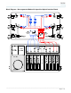

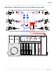
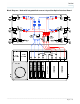
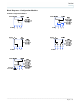

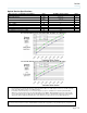
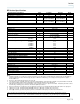
Table Of Contents
- Introduction
- Features
- Block Diagram – Non-segmented Node with 8-position Optical Interface Board
- Block Diagram – Segmented Node with 8-position Optical Interface Board
- Block Diagram – Node with bdr reverse & 6-position Optical Interface Board
- Block Diagram – Node with integrated bdr reverse & 8-position Optical Interface Board
- Block Diagrams – Configuration Modules
- Block Diagrams – Configuration Modules
- RF Section Specifications
- Ordering Information
- Strip Line
_________________________________________________________________________________________________________________
Page 9 of 16
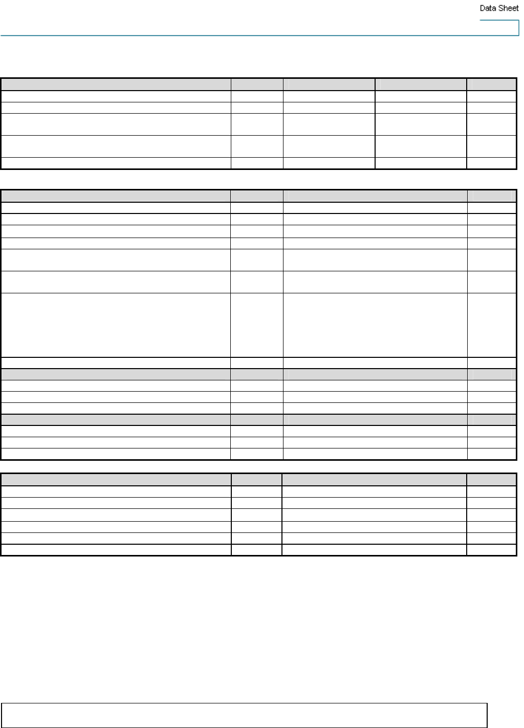
RF Section Specifications
General Station Performance Units Forward Reverse Notes
Pass Band MHz 52-1002 5-40
Input/Output Port Return Loss dB 17 16 1,5
Hum Modulation @ 12 A dB 70 (52-870 MHz)
60 (871-1002 MHz)
60 (5-10 MHz)
70 (11-40 MHz)
Hum Modulation @ 15 A dB 65 (52-870 MHz)
60 (871-1002 MHz)
60 (5-10 MHz)
65 (11-40 MHz)
Test Points (±0.5 dB) dB -20 -20
Forward Station Performance Units 7.5 dB I/S EQ w/3 dB I/S Pad Notes
Amplifier Type - GaAs FET
Operational Gain (minimum) dB 32 1
Frequency Response dB
0.5
1
Internal Tilt (±1 dB) dB 14.5 1,2
Port to Port Isolation dB 65 (52-750 MHz)
55 (751-1002 MHz)
1
Noise Figure @… 54 MHz
1002 MHz
dB 14.0
12.0
1
Reference Output Levels @… 1002 MHz
870 MHz
750 MHz
650 MHz
550 MHz
55 MHz
dBmV 49.5
47.5
45.7
44.0
42.5
35.0
Reference Output Tilt (55-1002 MHz) dB 14.5 2,3
78 NTSC channels (CW) with digital
6
Composite Triple Beat dB 78 4
Cross Modulation dB 68 4,8
Composite Second Order (high side) dB 70 4
94 NTSC channels (CW) with digital
7
Composite Triple Beat dB 73 4
Cross Modulation dB 65 4,7
Composite Second Order (high side) dB 67 4
Reverse Station Performance Units Reverse Notes
Amplifier Type - GaAs FET
Operational Gain (minimum) dB -2 5
Frequency Response dB
0.5
5
Internal Tilt (+/- 1 dB) dB 0 5
Path to Path Isolation dB 55 5
Noise Figure dB 7.5 5
Notes:
1. Forward performance is for station from output of optical Rx to node RF output port, with 0 dB pad in optical interface board (OIB), any
forward configuration module, 3 dB interstage (I/S) pad, 7.5 dB linear I/S EQ, factory select output pad, and signal director jumper.
Includes OIB losses.
2. Reference output tilt and internal tilt are both “Linear” tilt.
3. The forward reference output tilt specified is achieved via field installation of appropriate linear I/S EQ, in conjunction with the internal tilt
of the launch amplifier and the tilt associated with the optical link (transmitter/receiver combination).
4. Stated distortion performance is for launch amplifier section operated at reference output levels and tilts. Full station performance can be
determined by combining optic performance and launch amplifier performance.
5. Reverse performance is for station from reverse input port to input of reverse optical transmitter module, with 0 dB reverse input pad.
6. “Digital” refers to 550 - 1002 MHz loading with QAM carriers at -6 dB relative to analog video carrier levels.
7. “Digital” refers to 650 - 1002 MHz loading with QAM carriers at -6 dB relative to analog video carrier levels.
8. X-mod (@ 15.75 kHz) specified using 100% synchronous modulation and frequency-selective measurement device.
Unless otherwise noted, specifications reflect typical performance and are referenced to 68 F (20 C). Specifications are based
upon measurements made in accordance with SCTE/ANSI standards (where applicable), using standard frequency assignments.