
Data Sheet
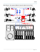

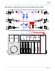
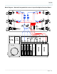
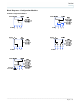

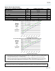
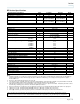
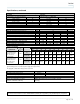
Table Of Contents
- Introduction
- Features
- Block Diagram – Non-segmented Node with 8-position Optical Interface Board
- Block Diagram – Segmented Node with 8-position Optical Interface Board
- Block Diagram – Node with bdr reverse & 6-position Optical Interface Board
- Block Diagram – Node with integrated bdr reverse & 8-position Optical Interface Board
- Block Diagrams – Configuration Modules
- Block Diagrams – Configuration Modules
- RF Section Specifications
- Ordering Information
- Strip Line
_________________________________________________________________________________________________________________
Page 8 of 16
Optical Section Specifications
Optical Section - Forward Receiver Module Units GS7000 Low Current RX Notes
Wavelength nm 1310 and 1550
Optical Input Range mW
dBm
0.5 to 1.6
-3 to +2
1
Pass Band MHz 52-1002
Frequency Response dB
0.5
2
Tilt ( 1.0 dB)
dB 0
Optical Input Test Point ( 10%)
V DC 1V/mW
Redundant Optical Rx Switching Threshold (± 1.0 dB) dBm -6
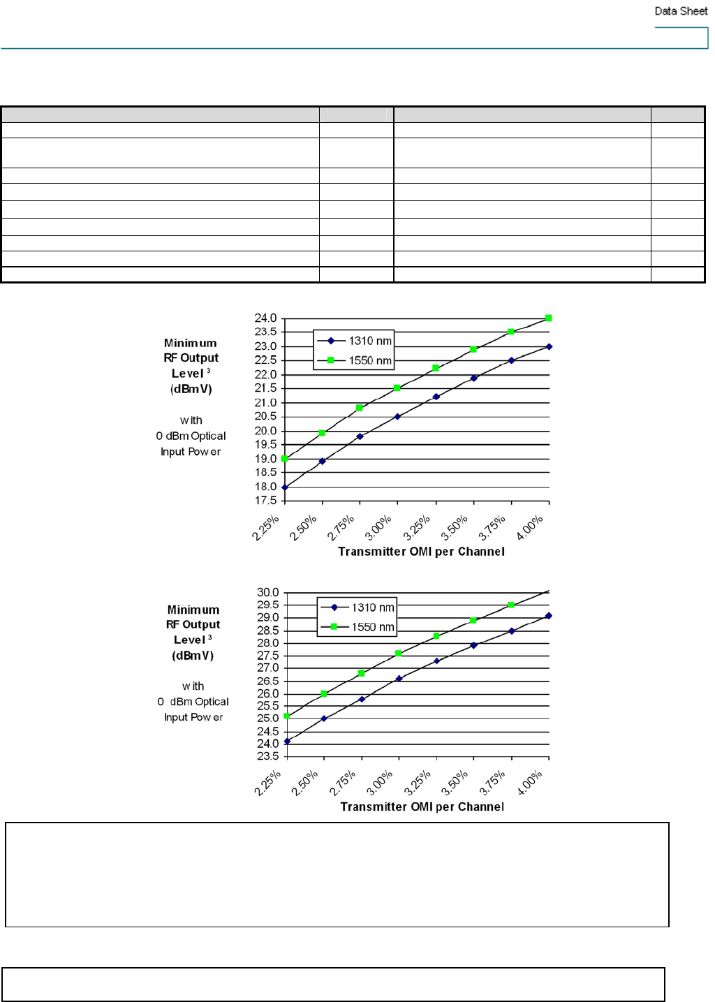
Rx RF Output Level at 0 dBm Optical Rx Power dBmV Refer to charts (below) 3
Rx RF Output Test Point (± 1.0 dB) dB - 20
Receiver RF Output Level Vs Transmitter OMI – Rx switch in -6 dB setting
Receiver RF Output Level Vs Transmitter OMI – Rx switch in 0 dB setting
For reverse optical transmitter and link performance, see the “Analog Reverse Optical Transmitters with Thermal Compensation” data sheet.
Unless otherwise noted, specifications reflect typical performance and are referenced to 68 F (20 C). Specifications are based
upon measurements made in accordance with SCTE/ANSI standards (where applicable), using standard frequency assignments.
Notes for Optical Section Specifications:
1. Receiver (Rx) has a 2-position RF attenuator switch (-6 dB and 0 dB). The -6 dB setting is used for 0 to +2 dBm optical Rx
power, the 0 dB setting is used for -3 to 0 dBm Rx power.
2. For forward receiver module only. Does not include frequency response contributions from forward optical transmitter.
3. Minimum receiver RF output level for the stated transmitter percent OMI/ch. (Optical Modulation Index per channel), with
receiver optical input power of 0 dBm, and specified Rx attenuator setting. To determine RF output levels at other optical
input power, add (or subtract) 2 dB in RF level for each 1 dB increase (or decrease) in receiver optical input power.