
Data Sheet
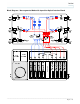

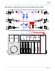
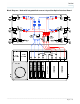
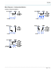

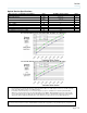
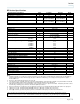
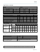
Table Of Contents
- Introduction
- Features
- Block Diagram – Non-segmented Node with 8-position Optical Interface Board
- Block Diagram – Segmented Node with 8-position Optical Interface Board
- Block Diagram – Node with bdr reverse & 6-position Optical Interface Board
- Block Diagram – Node with integrated bdr reverse & 8-position Optical Interface Board
- Block Diagrams – Configuration Modules
- Block Diagrams – Configuration Modules
- RF Section Specifications
- Ordering Information
- Strip Line
_________________________________________________________________________________________________________________
Page 10 of 16
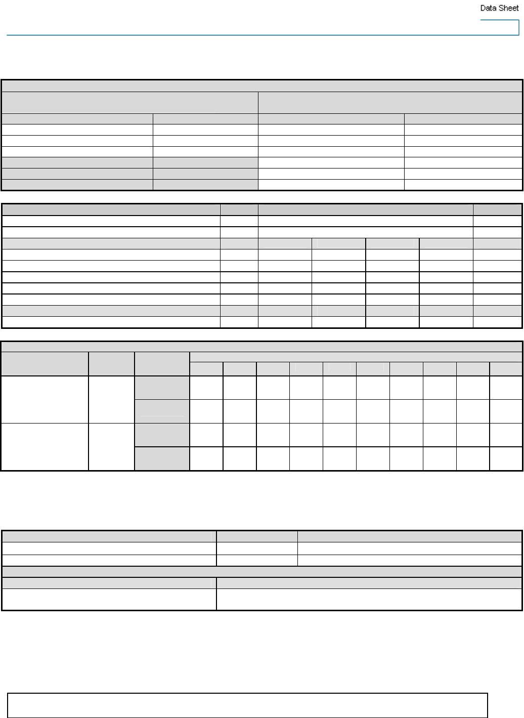
Specifications, continued
Station Delay Characteristics 40 / 52 Split
Forward
(Chrominance to Luminance Delay)
Reverse
(Group Delay in 1.5 MHz BW)
Frequency (MHz) Delay (nS) Frequency (MHz) Delay (nS)
55.25 - 58.83 16 5.0 - 6.5 35
61.25 - 64.83 8 6.5 - 8.0 15
67.25 - 70.83 5 8.0 - 9.5 7
35.5 - 37.0 11
37.0 - 38.5 14
38.5 - 40.0 20
Electrical Units Notes
Max. AC Through Current (continuous) Amps 15
Max. AC Through Current (surge) Amps 25
Component DC Power Consumption (typical)
@+24 VDC @ +8 VDC @ +5 VDC @ -6 VDC
Launch Amplifier (includes reverse amp) Amps 2.7 - 0.5 -
Status Monitoring Transponder Amps 0.01 - 0.2 -
GS7000 Low Current Optical Receiver Amps 0.12 - - -
Reverse Transmitter – High Gain FP Amps 0.09 - - 0.07
Reverse Transmitter – High Gain DFB Amps 0.09 - - 0.09
Power Supply DC Current Rating Amps 6.20 0.90 1.30 0.80
Station Powering Data
AC Voltage
GS7000 Node
I DC
(Amps at 24
VDC)
90 85 80 75 70 65 60 55 50 45
AC Current
(A)
1.3 1.4 1.4 1.4 1.5 1.5 1.6 1.8 1.9 2.2
with: 1 forward Rx,
1x2 forward config
module,1 reverse
Tx, 4x1 reverse
config module
2.93
Power (W) 94.0 93.9 93.6 93.5 93.4 93.4 93.3 93.4 93.5 94.0
AC Current
(A)
1.5 1.5 1.5 1.6 1.7 1.8 1.9 2.0 2.3 2.5
with: 2 forward Rx’s,
2x2 forward config
module,4 reverse
Tx’s, 4x4 reverse
config module
3.30
Power (W) 108.4 108.1 108.0 107.7 107.6 107.6 107.6 107.6 107.8 108.7
Data is based on stations configured with status monitoring transponder. AC currents specified are based on measurements made with
typical CATV type ferro-resonant AC power supply (quasi-square wave).
DC supply has a fixed under-voltage lockout of 33 V AC.
Environmental Units
Operating Temperature Range degrees
-40 F to 140 F (-40 C to 60 C)
Relative Humidity Range percent 5% to 95%
Mechanical
Housing Dimensions Weight
21.3 in. L x 11.6 in. H x 11.1 in. D
(541 mm x 295 mm x 282 mm)
Station with 4 RX, 4 TX, 2 power supplies: 50.0 lbs.
(22.7 Kg)
Unless otherwise noted, specifications reflect typical performance and are referenced to 68 F (20 C). Specifications are based
upon measurements made in accordance with SCTE/ANSI standards (where applicable), using standard frequency assignments.