
Data Sheet

Laser Link Ancillary Modules
4
Description
The Laser Link
RF Switch protects RF transmission paths by switching to a
redundant input in the event of a primary path failure. Switch position is
determined by an input TTL voltage or by the front panel membrane push
button.
The switch is designed to operate in conjunction with other Laser Link
devices that provide the state determining logic voltages. Each switch
device is housed in a half-width module, allowing for up to 14 switches to be
housed the Laser Link Mainframe, or four switches in the Laser Link Mini-
mainframe.
Benefits
• Improves system reliability
• Up to 14 half-width modules may be housed in a 5 RU space
• Front panel LEDs indicate switch position
• Accepts switch state determining logic from other Laser Link modules
Features
• Compact housing, half-width module
• Front panel membrane switch, determines switch position
• Front panel status indicators
• Output signal test point
• Redundant power option available
• Network Management (status monitoring) ready
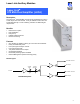
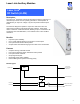
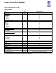
Block Diagram
Mode
Switch
Relay
Control
Relay
Operator Input
RF Input A
RF Input B
RF Common Output
-20 dB Test Point
TTL Control Input
Power Input
from Laser Link
Mainframe
LLRS RF Switch
Laser Link
RF Switch
(
LLRS
)