
User guide


Chapter 7. Configuring the Cisco 3012 InfiniBand to Ethernet gateway 147
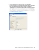
Figure 7-22 represents the test environment for demonstrating gateway redundancy. In this
example bridge group 1 (BG1) and bridge group 2 (BG2) will be put into Redundancy Group 1
(RG1).
Figure 7-22 Design showing Ethernet gateway redundancy in a single 3012
Note that for full redundancy, there would need to be two BCH InfiniBand switches, both ib0
and ib1 would be used on the servers, the Ethernet gateways would be in two separate
3012s, and there would be two upstream Ethernet switches. Since we are only trying to
demonstrate gateway redundancy, these extra elements are missing from our test
environment.
In this example, we are going to start from scratch, create two bridge groups and then add
them both to a new Redundancy group.
7.6.2 Summary of steps to create a redundant gateway design
Here, we provide a summary of the steps that we describe in the remainder of this section to
implement a redundant gateway design:
1. Make sure connections between the 3012 and the 4948 are down (step 1 on page 148).
2. Remove any old configurations from the last example (step 2 on page 148).
3. Add and enable the InfiniBand management interface (step 3 on page 148).
4. Create the bridge groups that are used for this redundant configuration (step 4 on
page 149).
5. Open up the Redundancy Group tabs in preparation for creating the Redundancy group
(step 5 on page 151).
ib0
BladeServer10
ib1
Cisco BCH 4X
IB Switch
Cisco 3012
Cisco 4948 Ethernet Switch
Access Access
VLAN VLAN
88 88
Gi1/16 Gi1/17
12 port IB – slot 15
12 port IB – slot 16
EGW4
EGW = Ethernet Gateway Module
BG1 = Bridge Group 1
Blue = InfiniBand
Green = Ethernet
Using default p_key – ff:ff
Ib0 = 172.16.225.10
Int VLAN 88
172.16.225.250
Untagged traffic
Eth int 4/1
IB int 4/1
BG1
EGW8
Eth int 8/1
IB int 8/2
BG2
Redundancy
Group 1
RG1
int mgmt-ib = 192.168.0.1/24
Ethernet Network
InfiniBand Network
BladeCenter H