Send documentation comments to nexus5kdocs@cisco.com CH A P T E R 2 Cisco Nexus 5000 Series Overview This chapter describes the Cisco Nexus 5000 series switches. This chapter includes the following sections: • Cisco Nexus 5020 Switch, page 2-1 • Cisco Nexus 5010 Switch, page 2-17 Cisco Nexus 5020 Switch This section describes the Cisco Nexus 5020 switches.
Chapter 2 Cisco Nexus 5000 Series Overview Cisco Nexus 5020 Switch Send documentation comments to nexus5kdocs@cisco.
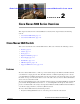
Chapter 2 Cisco Nexus 5000 Series Overview Cisco Nexus 5020 Switch Send documentation comments to nexus5kdocs@cisco.com Figure 2-2 Cisco Nexus 5020 Switch Front View Close-up 2 3 186261 1 1 Two power supplies 2 Five fan modules 3 System status LED The rear of the Cisco Nexus 5020 chassis has 40 fixed 10-Gigabit Ethernet ports, 2 slots for optional expansion modules, an Ethernet connector with 2 cross-connect ports and 2 management ports, a console port, and 2 AC power connectors.
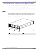
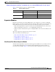
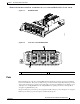
Chapter 2 Cisco Nexus 5000 Series Overview Cisco Nexus 5020 Switch Send documentation comments to nexus5kdocs@cisco.com Figure 2-4 shows a close-up view of the rear of the Cisco Nexus 5020 chassis. Figure 2-4 Cisco Nexus 5020 Switch Rear View Close-up 5 2 3 4 6 186263 7 1 1 System status LED 4 Slot 1, with 40 fixed 10-Gigabit Ethernet ports (highlighted in red).
Chapter 2 Cisco Nexus 5000 Series Overview Cisco Nexus 5020 Switch Send documentation comments to nexus5kdocs@cisco.com Table 2-1 lists the LED descriptions for all Ethernet LEDs.
Chapter 2 Cisco Nexus 5000 Series Overview Cisco Nexus 5020 Switch Send documentation comments to nexus5kdocs@cisco.com Figure 2-6 Fibre Channel Plus Ethernet Expansion Module 1 2 3 186384 4 5 Figure 2-7 shows the front of the Fibre Channel plus Ethernet expansion module. Figure 2-13 shows how ports are numbered on the Fibre Channel plus Ethernet expansion module.
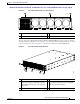
Chapter 2 Cisco Nexus 5000 Series Overview Cisco Nexus 5020 Switch Send documentation comments to nexus5kdocs@cisco.com Ethernet Expansion Module The Ethernet expansion module supports six 10-Gigabit Ethernet ports, four of which will have encryption capability. The Ethernet expansion module is a field-replaceable unit (FRU). Figure 2-8 shows the Ethernet expansion module.
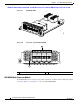
Chapter 2 Cisco Nexus 5000 Series Overview Cisco Nexus 5020 Switch Send documentation comments to nexus5kdocs@cisco.com N5K-M1008 GEM Figure 2-10 Front View of the N5K-M1008 GEM 189953 Figure 2-9 1 2 3 4 5 6 7 8 189954 1 2 1 Eight 1-, 2-, 4-Gbps Fibre Channel ports 2 LED N5K-M1060 Gatos Expansion Module The N5K-M1060 xpansion module provides 6 EA 1/2/4/8G line rate Fiber Channel, SFP+ based uplink connections. Figure 2-11 and Figure 2-12 show the N5K-M1060 GEM.
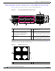
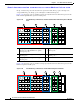
Chapter 2 Cisco Nexus 5000 Series Overview Cisco Nexus 5020 Switch Send documentation comments to nexus5kdocs@cisco.com N5K-M1060 GEM Figure 2-12 Front View of the N5K-M1060 GEM 196118 Figure 2-11 1 1 2 3 4 5 6 196117 1/2/4/8G FIBRE CHANNEL 2 1 Six 1-, 2-, 4-, 8-Gbps Fibre Channel ports 2 LED Ports Each individual port on the Cisco Nexus 5020 switch is numbered, and groups of ports are numbered based on their function. The ports are numbered top to bottom and left to right.
Chapter 2 Cisco Nexus 5000 Series Overview Cisco Nexus 5020 Switch Send documentation comments to nexus5kdocs@cisco.com Group 3 includes the ports in the bottom-most expansion module. Group 3 ports 1 through 4 are encrypted Ethernet ports. Group 3 ports 5 through 8 are Fibre Channel ports. Figure 2-13 shows how ports are numbered and grouped by function for both the fixed ports and the Fibre Channel plus Ethernet expansion module ports.
Chapter 2 Cisco Nexus 5000 Series Overview Cisco Nexus 5020 Switch Send documentation comments to nexus5kdocs@cisco.
Chapter 2 Cisco Nexus 5000 Series Overview Cisco Nexus 5020 Switch Send documentation comments to nexus5kdocs@cisco.com Table 2-2 Power Supply LED Descriptions (continued) Power Supply Condition Power LED Status Fail LED Status AC present, 3.3 voltage standby (VSB) on, and the power 1 Hz blinking supply unit is off. Off Power supply on and OK.
Chapter 2 Cisco Nexus 5000 Series Overview Cisco Nexus 5020 Switch Send documentation comments to nexus5kdocs@cisco.com Figure 2-17 Cisco Nexus 5020 Fan Module 186263 1 1 Fan module LED The bicolor fan module LED indicates the fan tray health. Green indicates normal operation, while amber indicates a fan failure.
Chapter 2 Cisco Nexus 5000 Series Overview Cisco Nexus 5020 Switch Send documentation comments to nexus5kdocs@cisco.com LED Descriptions Table 2-3 describes the LEDs for the Cisco Nexus 5020 switch. Table 2-3 LEDs for the Cisco Nexus 5020 Switch LED Location Chassis Front and back Chassis of chassis power and health Function Color Status Description Green Solid on All diagnostics pass. The module is operational. Off The module is not receiving power.
Chapter 2 Cisco Nexus 5000 Series Overview Cisco Nexus 5020 Switch Send documentation comments to nexus5kdocs@cisco.com Table 2-3 LEDs for the Cisco Nexus 5020 Switch (continued) LED Location Power supply Power supply (front) Function Color Status Description Power supply health Green Solid on Power supply is on and okay. Off No AC power to the power supply. Solid on Power supply failures, over voltage, over current, over temperature. Amber Blinking AC is present, 3.
Chapter 2 Cisco Nexus 5000 Series Overview Cisco Nexus 5020 Switch Send documentation comments to nexus5kdocs@cisco.com Supported SFP Transceivers The Cisco Nexus 5020 switch supports both SFP+ Ethernet transceivers and SFP Fibre Channel transceivers.
Chapter 2 Cisco Nexus 5000 Series Overview Cisco Nexus 5010 Switch Send documentation comments to nexus5kdocs@cisco.
Chapter 2 Cisco Nexus 5000 Series Overview Cisco Nexus 5010 Switch Send documentation comments to nexus5kdocs@cisco.com Features The Cisco Nexus 5010 switch is a 1RU, top-of-rack switch that provides Ethernet and Fibre Channel consolidation in a single physical cable. The Fibre Channel over Ethernet (FCoE) protocol is used to consolidate Ethernet and Fibre Channel traffic onto the same physical connection between the server and the switch.
Chapter 2 Cisco Nexus 5000 Series Overview Cisco Nexus 5010 Switch Send documentation comments to nexus5kdocs@cisco.com 1 2 Two power supplies Two fan modules Figure 2-20 shows a close-up view of the front of the switch.
Chapter 2 Cisco Nexus 5000 Series Overview Cisco Nexus 5010 Switch Send documentation comments to nexus5kdocs@cisco.
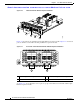
Chapter 2 Cisco Nexus 5000 Series Overview Cisco Nexus 5010 Switch Send documentation comments to nexus5kdocs@cisco.com Figure 2-22 shows a close-up view of the rear of the Cisco Nexus 5010 chassis. Figure 2-22 Cisco Nexus 5010 Switch Rear View Close-up 189952 1 2 3 5 4 6 1 System status LED 4 Slot 1, with 20 fixed 10-Gigabit Ethernet ports (highlighted in red).
Chapter 2 Cisco Nexus 5000 Series Overview Cisco Nexus 5010 Switch Send documentation comments to nexus5kdocs@cisco.com Table 2-7 lists the LED descriptions for all Ethernet LEDs.
Chapter 2 Cisco Nexus 5000 Series Overview Cisco Nexus 5010 Switch Send documentation comments to nexus5kdocs@cisco.com Figure 2-24 N5K-M1404 Gatos Expansion Module 1 2 3 186384 4 5 Figure 2-25 shows the front of the N5K-M1404 GEM . Figure 2-13 shows how ports are numbered on the GEM.
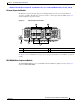
Chapter 2 Cisco Nexus 5000 Series Overview Cisco Nexus 5010 Switch Send documentation comments to nexus5kdocs@cisco.com Figure 2-26 N5K-M1600 GEM 3 3 1 1 2 3 4 5 6 186259 10 GIGABIT ETHERNET 2 4 1 10-Gigabit Ethernet ports 2 Module LED 3 10-Gigabit Ethernet ports See Figure 2-14 for an illustration of how ports are grouped and numbered on the Ethernet expansion module. N5K-M1008 Gatos Expansion Module The N5K-M1008 GEM supports 8 1/2/4G Fiber Channel, SFP-based uplink connection.
Chapter 2 Cisco Nexus 5000 Series Overview Cisco Nexus 5010 Switch Send documentation comments to nexus5kdocs@cisco.com Figure 2-28 Front View of the N5K-M1008 GEM 1 2 3 4 5 6 7 8 189954 1 2 1 Eight 1-, 2-, 4-Gbps Fibre Channel ports 2 LED N5K-M1060 Gatos Expansion Module The N5K-M1060 expansion module provides 6 EA 1-, 2-, 4-, 8-Gbps line rate Fiber Channel, SFP+ based uplink connections. Figure 2-27 shows the N5K-M1060 GEM.
Chapter 2 Cisco Nexus 5000 Series Overview Cisco Nexus 5010 Switch Send documentation comments to nexus5kdocs@cisco.com Figure 2-30 Front of the N5K-M1060 GEM 1 1 4 3 2 196117 1/2/4/8G FIBRE CHANNEL 6 5 2 1 Six 1-, 2-, 4-, 8-Gbps Fibre Channel ports 2 LED Ports Each individual port on the Cisco Nexus 5010 switch is numbered, and groups of ports are numbered based on their function. The ports are numbered top to bottom and left to right.
Chapter 2 Cisco Nexus 5000 Series Overview Cisco Nexus 5010 Switch Send documentation comments to nexus5kdocs@cisco.
Chapter 2 Cisco Nexus 5000 Series Overview Cisco Nexus 5010 Switch Send documentation comments to nexus5kdocs@cisco.com A Group 1, ports 1 through 8: 10-Gigabit Ethernet and 1-Gigabit Ethernet capable unencrypted ports B Group 1, ports 1 through 16: Unencrypted Ethernet ports C Group 1, ports 17 through 20: Encrypted Ethernet ports D Group 2, ports 1 through 8: Fibre Channel ports Power Supplies The Cisco Nexus 5010 switch uses a front-end power supply.
Chapter 2 Cisco Nexus 5000 Series Overview Cisco Nexus 5010 Switch Send documentation comments to nexus5kdocs@cisco.com Table 2-8 Power Supply LED Descriptions (continued) Power Supply Condition Power LED Status Fail LED Status Power supply warning events where the power supply continues to operate. These events include high temperature, high power, and slow fan. Off Blinking AC present, 3.3 voltage standby (VSB) on, and the power 1 Hz blinking supply unit is off. Off Power supply on and OK.
Chapter 2 Cisco Nexus 5000 Series Overview Cisco Nexus 5010 Switch Send documentation comments to nexus5kdocs@cisco.com Cisco Nexus 5010 Fan Module 189956 Figure 2-36 1 1 Fan module LED The bicolor fan module LED indicates the fan tray health. Green indicates normal operation, while amber indicates a fan failure. LED Descriptions Table 2-9 describes the LEDs for the Cisco Nexus 5010 switch.
Chapter 2 Cisco Nexus 5000 Series Overview Cisco Nexus 5010 Switch Send documentation comments to nexus5kdocs@cisco.com Table 2-9 LEDs for the Cisco Nexus 5010 Switch (continued) LED Location Function Color Status Description PSU Status Indicators Power supply (front) PSU Health (multi color) Green OFF No AC power to power supply Solid On Power supply on and OK Solid On Power supply failures, overvoltage, overcurrent, overtemperature Blinking AC present, 3.
Chapter 2 Cisco Nexus 5000 Series Overview Cisco Nexus 5010 Switch Send documentation comments to nexus5kdocs@cisco.com SFP+ Transceivers The enhanced Small-Form-Factor Pluggable (SFP+) 10-Gigabit Ethernet transceiver module is a bidirectional device with a transmitter and receiver in the same physical package. SeeTable 2-11. It has a 20-pin connector on the electrical interface and duplex LC connector on the optical interface.