
Operating instructions


Chapter 4. Cisco Systems Intelligent Gigabit Ethernet Switch Module architecture 21
Internal layer 2 traffic flow in the Cisco Systems IGESM
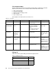
Figure 4-3 shows the internal layer 2 traffic flow in the Cisco Systems IGESM. The hard
coded filter in the Cisco Systems IGESM blocks all traffic between the external ports and the
Management Module ports. Two Cisco Systems IGESMs in the same BladeCenter chassis
exchange layer 2 frames across the Management Module. However, the Cisco Systems
IGESM blocks BPDUs which are switched by the Management Module.
This figure also indicates the following:
If CDP is enabled, two Cisco Systems IGESMs in the same BladeCenter chassis can
discover each other without connecting external ports. We can check connectivity
between them with show cdp neighbors command from the CLI.
The internal blade ports should not be on the same VLAN of the Management Module
ports. Otherwise, we face problems of duplicate IP addresses. See “Duplicate IP address:
part 1” on page 229 and “Duplicate IP address: part 2” on page 229.
Figure 4-3 Layer 2 frames flow in the Cisco Systems IGESM
Management
Module ports
4 External ports