
Operating instructions


20 Cisco Systems Intelligent Gigabit Ethernet Switch Module
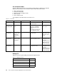
Figure 4-1 Cisco Systems IGESM architecture overview
We also discuss details about how the Cisco Systems IGESM in the BladeCenter chassis are
connected to the blade servers. Figure 4-2 shows the architecture for Ethernet connectivity.
The two Cisco Systems IGESMs can be housed within the BladeCenter chassis. Each Cisco
Systems IGESM provides four uplink ports, which can be grouped to support 802.3ad Link
Aggregation. The blade server has two NICs with NIC 1 connecting to Cisco Systems IGESM
1 and NIC 2 connecting to Cisco Systems IGESM 2. The links connecting the blade servers to
the Cisco Systems IGESMs are on the backplane of the BladeCenter chassis. The Cisco
Systems IGESM has two links to the Management Modules. Each link connects to a different
Management Module.
Figure 4-2 Ethernet connectivity
CIGESM
Module
14 ports
1000 Mbps
Internal links to
BladeServers
2 ports -100 Mbps
Internal links to the
Management Modules
4 ports
10/100/1000 Mbps
RJ45 links for external
network connections
1 port
RJ45 Service port
Serial console connection
on faceplate
CIGESM Connections
G0/1
G0/2
G0/3
G0/4
G0/5
G0/6
G0/7
G0/8
G0/9
G0/10
G0/11
G0/12
G0/13
G0/14
G0/15
G0/16
G0/17
G0/18
G0/19
G0/20
17
18
19
20
Blade1
Blade2
Blade3
Blade4
Blade5
Blade6
Blade7
Blade8
Blade9
Blade10
Blade11
Blade12
Blade13
Blade14
MM1
MM2
Serial
Cisco Systems
IGESM Module
Cisco Systems IGESM Connections
M
M
2
M
M
1
Blade
Servers
Management
Module
uplinks
IGESM2
17 18 19 20
IGESM2
17 18 19 2017 18 19 20
IGESM1
1 2 1 2
1 2
Blade
Server1
Blade
Server2
Blade
Server14