
Operating instructions


Chapter 8. Cisco Systems IGESM troubleshooting 209
If a critical condition is found during POST, the fault LED will be lit on back of IGESM.
A POST code of FF indicates that the IGESM booted successfully.
Additional messages may be found through a console port connection to the IGESM.
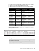
Figure 8-1 IGESM error codes
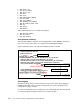
Figure 8-2 provides an example of what might be seen in the Management Module page
containing I/O Module error codes.
Figure 8-2 I/O Module POST results
Beyond normal bootup POST, the IGESM has certain diagnostics that can be executed from
the Management Module GUI.
Sub-Test Name Diagnostic
Indicator (in
Hex)
Failing
Functional Area
Failure
Criticality
CPU Cache
memory
0x01 Base Internal
Functions
Critical
Non-Cache
DRAM
0x02 Base Internal
Functions
Critical
Internal A SIC
packet memory
0x03-0x04 Base Internal
Functions
Critical
A SIC PCI
memory
0x05-0x06 Base Internal
Functions
Critical
data path test:
mgmt ports
0x07-0x08 Base Internal
Functions
Critical
VPD region read
test
0x09 Base Internal
Functions
Critical
Flash Memory in
Extended Post
0x0A Base Internal
Functions
Critical
Flash Memory in
regular POST
0x0B Base Internal
Functions
Critical
Data path test:
Internal GE ports
0x81-0x8E Internal Interface
Failure
Non-Critical
Data path test:
External ports
0xA 1- 0xA8 External Interface
Failure
Non-Critical
Important: Executing these diagnostics will result in the switch rebooting and should be
done only during a planned outage.
Note: The setting of Fast POST Enabled/Disabled in the I/O Module tasks Advanced
settings currently has no effect on the IGESM.