
Operating instructions


208 Cisco Systems Intelligent Gigabit Ethernet Switch Module
Gathering this information usually requires the involvement of several technical support
teams; for example, a network diagram usually comes from a network administration team,
and blade server configuration usually comes from a systems administration team.
From a support person’s perspective, answers to the following questions can also aid in this
process. Some basic examples:
– Is this the first time the problem has occurred? If not, how often does the issue occur?
– Can the problem be reproduced, or does it appear to be random?
– Has it ever worked in the past? If so, has anything changed recently in the network or
systems experiencing the issue?
– Has any corrective action been taken?
The responses should help in isolating the issue more quickly.
From here we begin to discuss some specifics of troubleshooting different kinds of issues
8.3 Troubleshooting suspected hardware issues
Troubleshooting defective hardware can be one of the easier issues to isolate, especially if it
is a consistent failure. The IGESM has a Fault LED on the rear (above the console port) that
is used to indicate a fault detected during POST (Power On Self Test). Table 8-2 shows some
details about this and other LEDs on the rear of the IGESM.
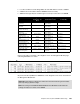
Table 8-2 IGESM LEDs
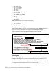
You can also use the Management Module browser to review the Power/Restart codes under
I/O Module tasks. Figure 8-1 provides information about error codes. Most critical errors
require an RMA to resolve.
Some rules with regard to these error codes:
The first critical error code will not be overwritten by subsequent errors.
A non-critical error will be overwritten by a subsequent critical error.
If POST fails a critical test, the bootloader will not load IOS. Switch stays in bootloader
(ROMMON) mode.
– ROMMON mode is also caused by a corrupt or missing IOS.
– Contact technical support for procedures for recovering from corrupt or missing IOS.
Indicator name Color Description
OK Green On solid when Switch module is powered up and operating normally.
Fault Amber Solid indicates that a fault has been detected somewhere on this
switch. Off otherwise.
Link OK Green Solid green when link status is up, off when link status is down. One
LED of this type for each external interface.
Tx/Rx/Activity Green Flashes green for traffic over the interface. One LED of this type for
each external interface.
Note: While the switch is executing POST, both the OK and Fault LEDs will be lit. When
POST completes successfully, the Fault LED will turn off.