
Operating instructions


198 Cisco Systems Intelligent Gigabit Ethernet Switch Module
Steps to configure for topology 2 Trunk Failover example
1. Configure global command.
2. Configure upstream port (or ports) or Etherchannel (poX).
3. Configure downstream port (or ports).
Configuring downstream before upstream will result in downstream ports going down until
upstream is configured.
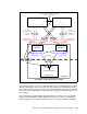
Trunk Failover configuration example for topology 1
CIGESM1# configure terminal
CIGESM1(config)# link state track 1
CIGESM1(config)# interface range po1 - 2
CIGESM1(config-if)# link state group 1 upstream
CIGESM1(config-if)# interface gi0/3
CIGESM1(config-if)# link state group 1 downstream
CIGESM1(config-if)# end
CIGESM1# write
Show current Trunk Failover operation
Use the show link state group command to show the operational state of Trunk Failover:
CIGESM1#show link state group detail
Link State Group: 1 Status: Enabled, Up
Upstream Interfaces : Po1(Up) Po2(Up)
Downstream Interfaces : Gi0/3(Up)
Link State Group: 2 Status: Disabled, Down
Upstream Interfaces :
Downstream Interfaces :
(Up):Interface up (Dwn):Interface Down (Dis):Interface disabled
In this example, if only Po1 or Po2 go down, spanning tree unblocks the other link as
necessary. Only when both Po1
and Po2 go down, will Gi0/3 be set to err-disable (down), at
which point NIC Teaming can then sense the failure and switch traffic out the other NIC.
Note the example above only shows one IGESM being configured. In most production
environments you would need to configure Trunk Failover on both IGESMs.
7.8 Serial over LAN feature description and configuration
This section provides a brief introduction to the Serial over LAN feature for the BladeCenter,
discusses certain rules, and provides an example of configuring the IGESM for SoL.
Serial over LAN requires configuring the Management Module, the IGESM and possibly the
BIOS and operating system of the blade server (depending on the model of blade server). For
a more detailed explanation of Serial over LAN operation and configuration of all of the
elements of SoL, reference the SoL Configuration Guide (link provided in the online resources
section later in this document).
7.8.1 Introduction to Serial over LAN
Serial over LAN (SoL) provides the ability to access blade servers via a special connection
from the Management Module, over a special VLAN and into the blade servers, for the
purpose of providing a text-only-based interface into the blade servers.