
Operating instructions


Chapter 7. Cisco Systems IGESM configuration and network integration 197
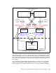
Figure 7-24 Topology 2 - Elements of Trunk Failover
This example in Figure 7-23 shows a single link state group on each IGESM (group 1) being
utilized. In this design, if the two ports in Po1 go down, spanning tree unblocks Po2. If both
Po1 and Po2 go down, Trunk Failover takes over and shuts down internal downstream defined
port(s). This alerts NIC Teaming to an upstream failure at which point Teaming switches to the
other IGESM.
This example shows a single VLAN to the Teamed NIC. It is possible to also carry multiple
VLANs to the Teamed NIC. If multiple VLANs are necessary, you must carry all VLANs to
both NICs and on all of the external uplinks as well as on Po1 between 6500-1 and 6500-3.
17 18 19 20
CIGESM Top
6500-1
1 2 3 4
6500-3
1 2 3 4
17 18 19 20
CIGESM Bot
Po1
Po2
Po3 Po2 Po3
NIC 1 NIC 2
BladeServer 3
Po2 Po2Po1Po1
BladeCenter
Topology 2 - Elements of Trunk Failover
Teamed
Active/Standby
Link state group 1
Upstream
Link state group 1
Upstream
Link state group 1
Downstream
Link state group 1
Downstream
Trunk Failover Config
NIC Teaming Config
Logical NIC Interface
VLAN X
VLAN X
Must be carried between IGESMs
via an external path
VLAN X
Must be carried
on uplinks from
IGESM
VLAN X
Must be carried
on uplinks from
IGESM