
Operating instructions


196 Cisco Systems Intelligent Gigabit Ethernet Switch Module
down internal downstream defined port(s). This alerts NIC Teaming to an upstream failure, at
which point NIC Teaming switches to the other IGESM.
This example shows a single VLAN to the Teamed NIC. It is possible to also carry multiple
VLANs to the Teamed NIC. If multiple VLANs are necessary, you must carry all VLANs to
both NICs and on all of the external uplinks as well as on Po1 between 6500-1 and 6500-3.
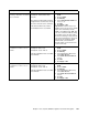
Steps to configure for topology 1 Trunk Failover example
1. Configure global command.
2. Configure upstream port (or ports) or Etherchannel (poX).
3. Configure downstream port (or ports).
Configuring downstream before upstream will result in downstream ports going down until
upstream is configured.
Trunk Failover configuration example for topology 1
CIGESM1# configure terminal
CIGESM1(config)# link state track 1
CIGESM1(config)# interface po1
CIGESM1(config-if)# link state group 1 upstream
CIGESM1(config-if)# interface gi0/3
CIGESM1(config-if)# link state group 1 downstream
CIGESM1(config-if)# end
CIGESM1# write
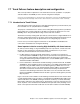
Show current Trunk Failover operation
Use the show link state group command to show the operational state of Trunk Failover:
CIGESM1#show link state group detail
Link State Group: 1 Status: Enabled, Up
Upstream Interfaces : Po1(Up)
Downstream Interfaces : Gi0/3(Up)
Link State Group: 2 Status: Disabled, Down
Upstream Interfaces :
Downstream Interfaces :
(Up):Interface up (Dwn):Interface Down (Dis):Interface disabled
In this example, when all four ports on Po1 go down, Gi0/3 will be set to err-disable (down) at
which point NIC Teaming can then sense the failure and switch traffic out the other NIC.
Note the example above only shows one IGESM being configured. In most production
environments you would need to configure Trunk Failover on both IGESMs.
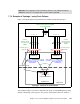
7.7.3 Example of Topology 2 using Trunk Failover
Figure 7-23 logically depicts using Trunk Failover and NIC Teaming with Topology 2.