
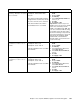
Operating instructions


Chapter 7. Cisco Systems IGESM configuration and network integration 195
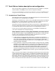
7.7.2 Example of Topology 1 using Trunk Failover
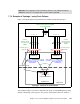
Figure 7-23 logically depicts using Trunk Failover and NIC Teaming with Topology 1.
Figure 7-23 Topology 1 - Elements of Trunk Failover
This example in Figure 7-23 shows a single link state group on each IGESM (group 1) being
utilized. In this design, if all four ports in Po1 go down, trunk Failover takes over and shuts
Important: The configuration of the Trunk Failover feature is only available through the
IGESM CLI and not is not configure-able or monitor-able through CMS.
17 18 19 20
CIGESM Top
6500-1
1 2 3 4
6500-3
1 2 3 4
17 18 19 20
CIGESM Bot
Po1
Po2
Po2
NIC 1 NIC 2
BladeServer 3
Po1Po1
BladeCenter
Topology 1 - Elements of Trunk Failover
Teamed
Active/Standby
Link state group 1
Upstream
Link state group 1
Upstream
Link state group 1
Downstream
Link state group 1
Downstream
Trunk Failover Config
NIC Teaming Config
Logical NIC Interface
VLAN X
VLAN X
Must be carried between IGESMs
via an external path
VLAN X
Must be carried
on uplinks from
IGESM
VLAN X
Must be carried
on uplinks from
IGESM